
Temank US-POW-LVM3.2K-24V-YF
Temank 3200W Solar Inverter User Manual
Model: US-POW-LVM3.2K-24V-YF
1. Introduction
This manual provides essential information for the safe and efficient operation of your Temank 3200W Solar Inverter. This off-grid power inverter converts 24V DC to 120V AC and features a built-in 80A MPPT charge controller. It is designed for compatibility with both lead-acid and lithium batteries, supporting a maximum PV input of 108V. Please read this manual thoroughly before installation and use.
2. Product Overview
The Temank 3200W Solar Inverter is a versatile unit combining an inverter, solar charger, and battery charger to offer uninterruptible power support. Its comprehensive LCD display provides user-configurable and easily accessible button operations such as battery charging current, AC/solar charger priority, and acceptable input voltage based on different applications.

Figure 2.1: Front view of the Temank 3200W Solar Inverter, showing the display screen and control buttons.
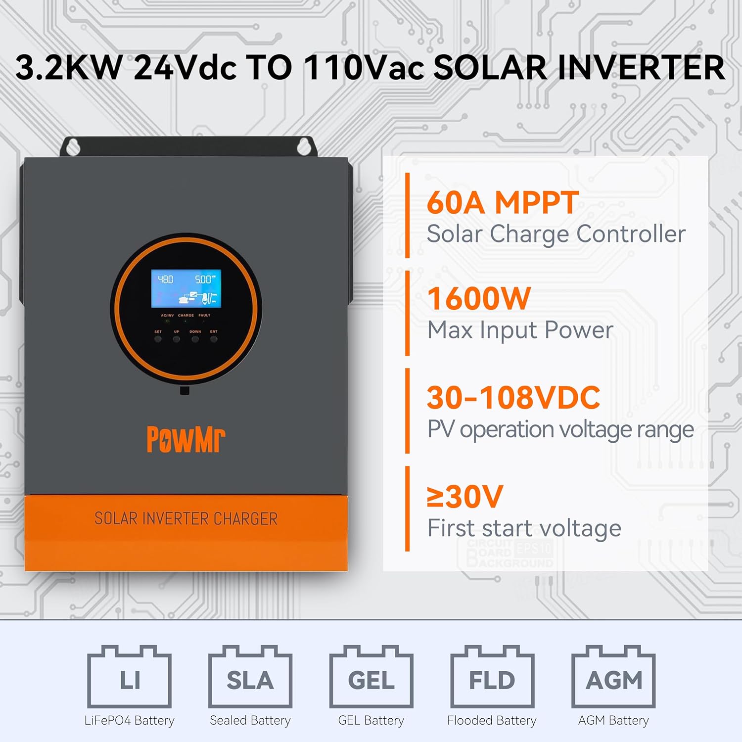
Figure 2.2: Diagram illustrating key features: 60A MPPT Solar Charge Controller, 1600W Max Input Power, 30-108VDC PV operation voltage range, and compatibility with various battery types (LiFePO4, Sealed, GEL, Flooded, AGM).

Figure 2.3: Diagram showcasing 360-degree multi-protection functions including overload, charge short, AC reverse, short-circuit, bypass over current, battery over voltage, battery low voltage, and parallel connection error protection.
3. Setup
3.1 Unpacking and Inspection
Upon receiving the inverter, carefully unpack it and inspect for any shipping damage. Ensure all components listed in the packing list are present. If any damage or missing parts are found, contact your dealer immediately.
3.2 Mounting the Inverter
Choose a suitable location for mounting the inverter. It should be a dry, well-ventilated area, away from direct sunlight, heat sources, and flammable materials. Ensure adequate clearance around the unit for proper airflow.
3.3 Wiring Connections
All wiring should be performed by a qualified electrician in accordance with local electrical codes. Ensure all connections are secure and properly insulated to prevent short circuits and electrical hazards.

Figure 3.1: Detailed wiring diagram for AC input, AC output, and PV input, showing connections to generator, utility, solar panels, and 24V battery. This diagram is for reference only; actual wiring may vary based on installation.
- Battery Connection: Connect the 24V battery bank to the inverter's battery terminals. Ensure correct polarity. Recommended battery capacity is 200AH.
- PV Input Connection: Connect your solar panel array to the PV input terminals. Ensure the total open circuit voltage (VOC) is within the 30-108V range and the maximum PV input power does not exceed 1600W.
- AC Input Connection: Connect the AC utility grid or generator to the AC input terminals. The acceptable AC input voltage range is 90-140Vac.
- AC Output Connection: Connect your AC loads (e.g., home appliances) to the AC output terminals. The inverter provides 120V AC output.
- Grounding: Ensure the inverter is properly grounded to prevent electrical shock.
4. Operating Instructions
4.1 Initial Power-Up
After all connections are securely made, turn on the battery breaker first, then the AC input breaker (if applicable), and finally the inverter's power switch. The LCD display will illuminate, showing system status.
4.2 Display and Control Panel
The inverter features an LCD display and control buttons (SET, UP, DOWN, ENT) for monitoring and configuring operational parameters.
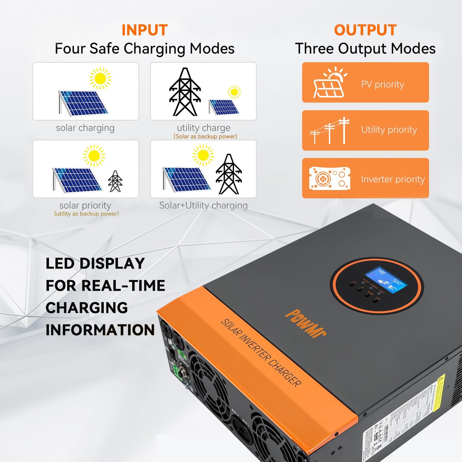
Figure 4.1: Visual representation of four safe charging input modes (solar, utility, solar priority, solar+utility) and three output modes (PV priority, utility priority, inverter priority), along with the LED display for real-time information.
4.3 Operating Modes
The inverter supports various operating modes, which can be configured via the control panel:
- PV Priority: Solar power is the primary source for loads and battery charging. Utility/AC input acts as a backup.
- Utility Priority: Utility/AC input is the primary source. Solar power is used when utility is unavailable or for charging.
- Inverter Priority: Battery power is the primary source for loads. Utility/AC input is used for charging and as a backup when battery voltage is low.
4.4 Charging Modes
The built-in MPPT charge controller manages battery charging from solar panels and/or AC utility. Available charging modes include:
- Solar Charging: Charges batteries solely from solar panels.
- Utility Charge (Solar as backup power): Primarily charges from utility, with solar as backup.
- Solar Priority (Utility as backup power): Primarily charges from solar, with utility as backup.
- Solar+Utility Charging: Charges from both solar and utility simultaneously for faster charging.
5. Maintenance
Regular maintenance ensures the longevity and optimal performance of your Temank Solar Inverter.
- Cleaning: Periodically clean the exterior of the inverter with a dry cloth. Ensure ventilation openings are free from dust and debris.
- Fan Operation: The inverter features smart variable speed fans that adjust based on ambient temperature. Ensure these fans are not obstructed.

Figure 5.1: Rear view of the inverter with smart variable speed fans, emphasizing their function in adjusting rotation speed based on ambient temperature and environmental conditions.
- Connection Check: Annually inspect all wiring connections for tightness and signs of corrosion.
- Battery Health: Monitor battery voltage and health regularly, especially for lead-acid batteries.
6. Troubleshooting
This section provides solutions to common issues you might encounter with your inverter. For problems not listed here, please contact customer support.
| Problem | Possible Cause | Solution |
|---|---|---|
| Inverter not turning on | No battery connection; Battery voltage too low; Power switch off; Blown fuse/breaker. | Check battery connections; Charge battery; Turn on power switch; Check and replace fuse/reset breaker. |
| No AC output | Overload; Over-temperature; Battery low/high voltage; AC output breaker tripped. | Reduce load; Allow inverter to cool down; Check battery voltage; Reset AC output breaker. |
| Battery not charging | PV input too low/high; Solar panels not connected; AC input not present (if AC charging); MPPT controller fault. | Check PV voltage and connections; Ensure AC input is available; Contact support if MPPT fault persists. |
| Unusual noise from inverter | Loose components; Overload; Fan malfunction. | Check for loose parts; Reduce load; Ensure fan is not obstructed and operating correctly. |
7. Specifications
| Parameter | Value |
|---|---|
| Brand | Temank |
| Model | US-POW-LVM3.2K-24V-YF |
| Model Name | 3200W |
| Wattage | 3200 watts |
| Power Source Type | Solar Powered |
| Battery Capacity | 200 Amp Hours (Recommended) |
| Max. PV Input Voltage | 108 Volts |
| Max. PV Input Power | 1600W |
| MPPT Charge Controller | 80A |
| AC Output Voltage | 120V AC |
| Frequency | 60 Hz |
| Item Weight | 6.79 kg |
| Product Dimensions (L x W x H) | 37.8 x 28 x 10.3 cm |
| Display Type | LCD+LED |
| Included Components | Instruction Manual, Solar Inverter |
| Recommended Uses | Boat, Home, Office, Vehicle |
8. Warranty and Support
For warranty information or technical support, please refer to the documentation provided with your purchase or contact Temank customer service directly. Details regarding warranty periods and support channels are typically included with the product packaging or available on the manufacturer's official website.
Related documentsUS-POW-LVM3.2K-24V-YF


Ask a question about this manual
Ask about setup, troubleshooting, compatibility, parts, safety, or missing instructions. Manuals+ will review the question and use this page’s manual context to help answer it.