
Introduction
This manual provides essential information for the safe and efficient operation of the Generic AI-7481 PID Temperature Controller. Please read these instructions carefully before installation and use to ensure proper functionality and to prevent damage to the device or connected equipment.
Product Overview
Front Panel
The front panel features a dual LED display for Process Value (PV) and Set Value (SV), along with control buttons for configuration and operation. The PV display shows the current measured temperature, while the SV display shows the target temperature.

Image: Front view of the AI-7481 PID Temperature Controller, showing the dual digital display and control buttons.
Rear Panel and Connections
The rear panel provides terminal blocks for input sensors, control outputs (Relay/SSR), and power supply connections. Ensure all wiring is correct and secure before powering on the device.

Image: Rear view of the AI-7481 PID Temperature Controller, illustrating the various terminal connections for power, sensor input, and control outputs.
Technical Specifications
| Feature | Description |
|---|---|
| Model | AI-7481 |
| Input Types | Thermocouple (TC) J, K, R, S, T, N, B; RTD Pt100 |
| Resolution | TC: 1°C; Pt-100: 1°C / 0.1°C |
| Sampling Rate | 250 milliseconds |
| Accuracy | 0.3% Full Scale (FS) |
| Control Output | Relay: 5A @ 250 VAC / 30 VDC; SSR: 12 VDC @ 30mA |
| Supply Voltage | 90 to 270 VAC (Universal); 24 VDC available on request |
| Operating Temperature | 0°C to 50°C |
| Storage Temperature | -20°C to 75°C |
| Humidity | 95% RH (Non-condensing) |
| Dimensions (H x W x D) | 48 x 48 x 78 mm (approx. 15 x 15 x 15 cm) |
| Material | Plastic |
| Display Type | LED |
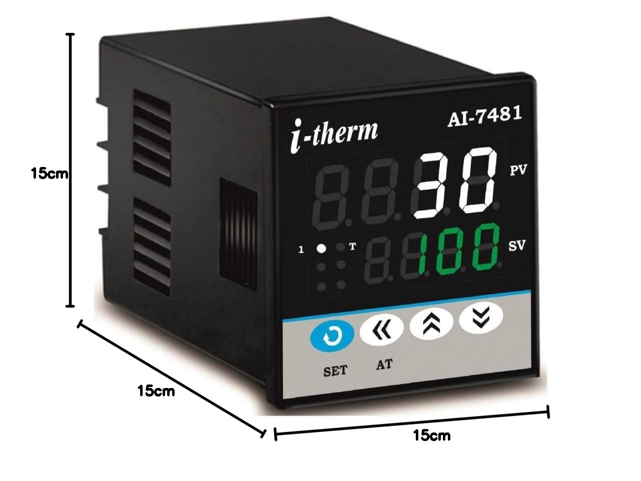
Image: Dimensional drawing of the AI-7481 PID Temperature Controller, indicating its physical size.
Installation and Setup
Mounting
The controller is designed for panel mounting. Ensure adequate space for ventilation and wiring connections. Avoid locations with excessive vibration, dust, moisture, or corrosive gases to ensure optimal performance and longevity.
Wiring Connections
Refer to the wiring diagram on the rear panel of the device and the image provided in the Product Overview section. Ensure all connections are secure and correct before applying power.
- Power Supply: Connect the main power supply (90-270 VAC or 24 VDC if applicable) to the designated terminals.
- Sensor Input: Connect your chosen thermocouple (J, K, R, S, T, N, B) or RTD (Pt100) sensor to the input terminals. Observe polarity for thermocouples.
- Control Output: Connect your heating or cooling element to the Relay or SSR output terminals as required. Ensure the load current does not exceed the specified limits (5A for Relay, 30mA for SSR drive).
Warning: Incorrect wiring can damage the device and pose safety risks. Consult a qualified electrician if unsure.
Operating the Controller
Power On
Once wired correctly, apply power. The controller will perform a self-test, and the display will show the Process Value (PV) and Set Value (SV).
Setting the Set Value (SV)
- Press the SET button once. The SV display will begin to flash.
- Use the Up (▲) and Down (▼) arrow buttons to adjust the desired temperature.
- Press SET again to confirm the new SV. The display will stop flashing.
Parameter Configuration
Advanced parameters such as PID constants, input type, output type (Relay/SSR), and alarm settings can be accessed through a specific key combination (e.g., long press SET or a combination of SET and arrow keys). Refer to the full technical manual for detailed parameter settings.
Control Features
- Selectable Control Output: The controller supports both Relay and SSR drive outputs, configurable based on application needs.
- Overshoot Control Protection: Designed to minimize temperature overshoot, ensuring stable and precise control.
- Single Step Ramp: Allows for a gradual increase or decrease in temperature to the set point.
- Time Delay for Compressor: Provides a configurable delay for compressor control applications, protecting the compressor from rapid cycling.
Maintenance
The AI-7481 PID Temperature Controller requires minimal maintenance to ensure long-term reliable operation.
- Cleaning: Periodically clean the front panel with a soft, dry cloth. Do not use abrasive cleaners or solvents, as these can damage the display or casing.
- Inspection: Regularly inspect wiring connections for looseness or signs of damage. Ensure all terminals are securely fastened.
- Environment: Ensure the operating environment remains within specified temperature and humidity ranges to prolong the device's lifespan.
Troubleshooting
| Problem | Possible Cause | Solution |
|---|---|---|
| Controller does not power on | No power supply; incorrect wiring; blown fuse | Check power connections; verify wiring; replace fuse if necessary. |
| Incorrect temperature reading (PV) | Sensor faulty; incorrect sensor type selected; sensor wiring incorrect | Check sensor for damage; verify sensor type in settings; inspect sensor wiring for proper connection and polarity. |
| Output not activating/deactivating | Output type misconfigured; set value not reached; faulty output component | Verify output type (Relay/SSR) in settings; check SV and PV values; test output component if possible. |
| Temperature unstable/overshooting | PID parameters not tuned; external disturbances | Perform auto-tuning (AT function) or manually adjust PID parameters; ensure stable operating environment. |
Warranty and Customer Support
Warranty Information
This product comes with a 1-year warranty from the date of purchase, covering manufacturing defects. Please retain your purchase receipt for warranty claims.
Customer Support
For technical assistance, troubleshooting, or warranty inquiries, please contact the manufacturer:
Manufacturer: SYSTEM CONTROLS
Address: 27, Hareram Industrial Estate, I.B. Patel Road, Opp. Shanta Ind. Est., Goregaon East, Mumbai 400063, India
Contact Number: +91 9324466415


