
1. Introduction
This manual provides detailed instructions for the installation, operation, and maintenance of your Aoleaby JK Smart Active Balance Battery Management System (BMS) model BD6A24S15P. This BMS is designed to protect and optimize the performance of various battery chemistries, including Lifepo4, Li-Ion, and LTO, across a range of cell configurations (4S to 24S).
Key features of this Smart BMS include:
- Active Balance: Balances voltage differences between battery cells, enhancing battery usage efficiency up to 99% and extending battery lifespan.
- Comprehensive Protection: Safeguards against over-charge, over-discharge, over-current, short circuit, and includes low-temperature charging cutoff.
- Bluetooth (BT) Communication: Allows real-time battery status monitoring and BMS settings adjustment via a dedicated mobile application.
- Optional CANBUS Chip: Available in some models for advanced communication (C: BMS With CANBUS chip Built-in).
- Optional Heating Function: Available in some models to manage battery temperature during cold conditions (H: BMS With Heat Function).
2. Package Contents
Please verify that all items are present in your package:
- JK Smart Active Balance BMS (BD6A24S15P) with built-in Bluetooth (BT) module
- Temperature Sensor (40cm)
- Balance Wires (75cm)
- Active Switch (15cm)
- Heating Cable (Only included with BMS models featuring the Heat Function)

Figure 2.1: The Aoleaby JK Smart Active Balance BMS shown with its standard accessories, including the NTC temperature sensor, active switch, and balance cables. The heating cable is included only with models that support the heating function.
3. Specifications
The Aoleaby JK Smart Active Balance BMS BD6A24S15P offers the following technical specifications:
| Feature | Specification |
|---|---|
| Model | BD6A24S15P |
| Function | Bluetooth (BT) / RS485 Communication |
| Balancing Current | 0.6A - 2A Active Balance Current |
| Supported Battery Strings | 8S - 24S (Supports 4S, 8S, 12S, 13S, 14S, 16S, 17S, 20S, 24S configurations) |
| Charge/Discharge Current | Up to 150A (Continuous), 350A (Peak) |
| Supported Battery Types | Li-ion, Lifepo4, LTO |
| Protection Features | Over-charge, Over-discharge, Over-current, Short Circuit, Low Temperature Charging Cutoff |
| Heating Function (Optional) | Max heating power 200W (100W for B2A8S20P variant) |
| Item Weight | 2.2 pounds (approximately 1000 grams) |
| Package Dimensions | 1.18 x 0.79 x 0.39 inches |

Figure 3.1: Front view of the Aoleaby JK Smart Active Balance BMS BD6A24S15P, displaying key operational specifications.

Figure 3.2: Rear view of a Smart Active Balance BMS, providing additional technical details and a QR code for the companion application.
4. Setup & Installation
Careful installation is crucial for the safe and effective operation of your BMS. Please follow these steps precisely.
4.1. Wiring Connections
Refer to the wiring diagram below for proper connection of the BMS to your battery pack. Ensure all connections are secure and correctly polarized.

Figure 4.1: Main wiring diagram for the Aoleaby JK Smart Active Balance BMS, illustrating the P- (load/charge negative) and B- (battery negative) connections, and the balance port.
- Connect B- (Battery Negative): Connect the main negative terminal of your battery pack to the B- terminal on the BMS (typically blue wires).
- Connect P- (Load/Charge Negative): Connect the negative terminal for your load and charger to the P- terminal on the BMS (typically black wires).
- Connect Balance Wires: Carefully connect the balance wires from each cell of your battery pack to the corresponding balance port on the BMS. Ensure the correct order (B1, B2, B3... B+). Incorrect balance wire connection can damage the BMS or battery.
- Connect Temperature Sensor: Plug the temperature sensor into its designated port on the BMS. Position the sensor to accurately monitor battery temperature.
- Connect Active Switch: Connect the active switch to its port. This switch is used to activate/deactivate the BMS.
4.2. Heating Function (Optional)
For BMS models equipped with the heating function:
- The green 5-PIN cable of the heating cable must be connected to the heating pad.
- The remaining black and red cables of the heating cable should be connected to a smart charger.
- When the smart charger is linked to the BMS, it will detect the battery temperature via the BMS and automatically manage the charging status, activating heating if the battery temperature falls below the low-temperature charge protection threshold (a parameter configurable within the APP).
- Heating power is determined by battery voltage (U) and heating film resistance (R), calculated as U*U/R. The maximum current for the heating function is 3A.
4.3. Mobile Application Installation
The JK Smart BMS utilizes a dedicated mobile application for monitoring and configuration. Scan the QR code on the BMS unit or use the link below to download the official application.
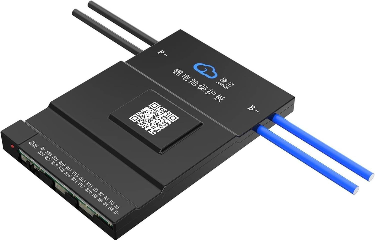
Figure 4.2: Angled view of the BMS, highlighting the QR code for app download.
Download the JK BMS App: http://qr17.cn/BApbC0
5. Operating Instructions
5.1. Initial Power-Up
After completing all wiring connections, activate the BMS using the active switch. The BMS should power on, and you should be able to connect to it via Bluetooth using the mobile application.
5.2. Using the Mobile Application
The JK BMS mobile application allows you to:
- Monitor real-time battery parameters: individual cell voltages, total pack voltage, current, temperature, state of charge (SOC).
- View protection status: check for over-voltage, under-voltage, over-current, and temperature alarms.
- Configure BMS settings: adjust protection thresholds, balancing parameters, and other operational settings.
- Control charging and discharging (if applicable to your setup).
5.3. Active Balancing
The BMS continuously monitors cell voltages and initiates active balancing when voltage differences are detected. This process helps to equalize cell voltages, preventing premature aging of individual cells and maximizing the overall capacity and lifespan of the battery pack.
5.4. Protection Functions
The BMS provides critical protection for your battery:
- Over-charge Protection: Prevents cells from being charged beyond their safe voltage limit.
- Over-discharge Protection: Prevents cells from being discharged below their safe voltage limit.
- Over-current Protection: Shuts off power if the discharge or charge current exceeds safe limits.
- Short Circuit Protection: Immediately cuts off power in case of a short circuit.
- Low Temperature Charging Cutoff: Prevents charging at temperatures that could damage the battery cells.
6. Maintenance
To ensure the longevity and optimal performance of your Aoleaby JK Smart Active Balance BMS and battery system, consider the following maintenance guidelines:
- Regular Inspection: Periodically inspect all wiring connections for signs of corrosion, looseness, or damage. Ensure balance wires are securely connected.
- Cleanliness: Keep the BMS unit clean and free from dust, dirt, and moisture. Use a dry, soft cloth for cleaning.
- Firmware Updates: Check the mobile application or manufacturer's website for any available firmware updates for the BMS. Updates can improve performance and add new features.
- Environmental Conditions: Operate the BMS and battery within their specified temperature and humidity ranges. Avoid extreme conditions.
- Battery Health Monitoring: Regularly use the mobile application to monitor individual cell voltages and overall battery health. Address any anomalies promptly.
7. Troubleshooting
If you encounter issues with your Aoleaby JK Smart Active Balance BMS, refer to the following common problems and solutions:
| Problem | Possible Cause | Solution |
|---|---|---|
| BMS does not power on | Active switch off, incorrect main power wiring, faulty BMS | Ensure active switch is on. Verify B- and P- connections. Check battery voltage. Contact support if issue persists. |
| Cannot connect via Bluetooth | BMS not powered, Bluetooth disabled on phone, app issues, out of range | Ensure BMS is on. Enable Bluetooth on your device. Restart app/phone. Move closer to BMS. |
| Cells are not balancing | Balance wires incorrectly connected, significant cell voltage difference, balancing current setting | Verify balance wire order and connection. Allow time for balancing. Check balancing current settings in the app. |
| BMS triggers protection (e.g., over-voltage, under-voltage) | Battery cell outside safe limits, protection thresholds set too low/high, faulty sensor | Check individual cell voltages in the app. Review and adjust protection parameters in the app if necessary. Inspect sensors. |
| Heating function not working | Incorrect heating cable wiring, temperature above threshold, faulty heating pad/sensor | Verify heating cable connections (green to pad, red/black to charger). Check app for temperature readings and low-temp charge protection settings. |
For more complex issues or if the problem persists, please refer to the support section.
8. Warranty and Support
8.1. Warranty Information
Specific warranty details for the Aoleaby JK Smart Active Balance BMS are typically provided at the point of purchase or within the product packaging. Please retain your proof of purchase for warranty claims. For detailed warranty terms and conditions, contact your retailer or the manufacturer directly.
8.2. Customer Support
If you require technical assistance, have questions about installation, or need help with troubleshooting that is not covered in this manual, please contact Aoleaby customer support or your product vendor. When contacting support, please have your product model (BD6A24S15P) and purchase information readily available.
You may also find additional resources and frequently asked questions on the manufacturer's official website or within the JK BMS mobile application.