1. Introduction
The Mastech MS5908A Circuit Analyzer is a professional-grade instrument designed for comprehensive electrical circuit testing. It provides accurate measurements for AC voltage, impedance, frequency, and performs critical RCD and GFCI tests, ensuring electrical safety and proper circuit functionality. This manual provides detailed instructions for the safe and effective use of your MS5908A.

Figure 1: Front view of the Mastech MS5908A Circuit Analyzer, showing the LCD display and control buttons.
2. Safety Information
WARNING: Always read and understand all safety warnings and instructions before using this instrument. Failure to follow these instructions may result in electric shock, fire, or serious injury.
- Ensure the device is suitable for the voltage and current levels of the circuit being tested. The MS5908A is designed for 110V US plug systems.
- Do not use the device if it appears damaged or is operating abnormally.
- Always wear appropriate personal protective equipment (PPE), such as insulated gloves and safety glasses, when working with electrical circuits.
- Do not operate the device in wet conditions or in explosive atmospheres.
- Verify the correct connection of the device before initiating any test.
- Keep hands and fingers away from live terminals.
- Only qualified personnel should perform electrical testing.
3. What's in the Box
Upon opening the package, please verify that all items listed below are present and in good condition:
- 1 x Mastech MS5908A Circuit Analyzer
- 2 x LR44 batteries (included)
- 1 x Power Cord / Carry Bag (as indicated in packaging information)
- 1 x Calibration Certificate
- 1 x Quick Start Guide
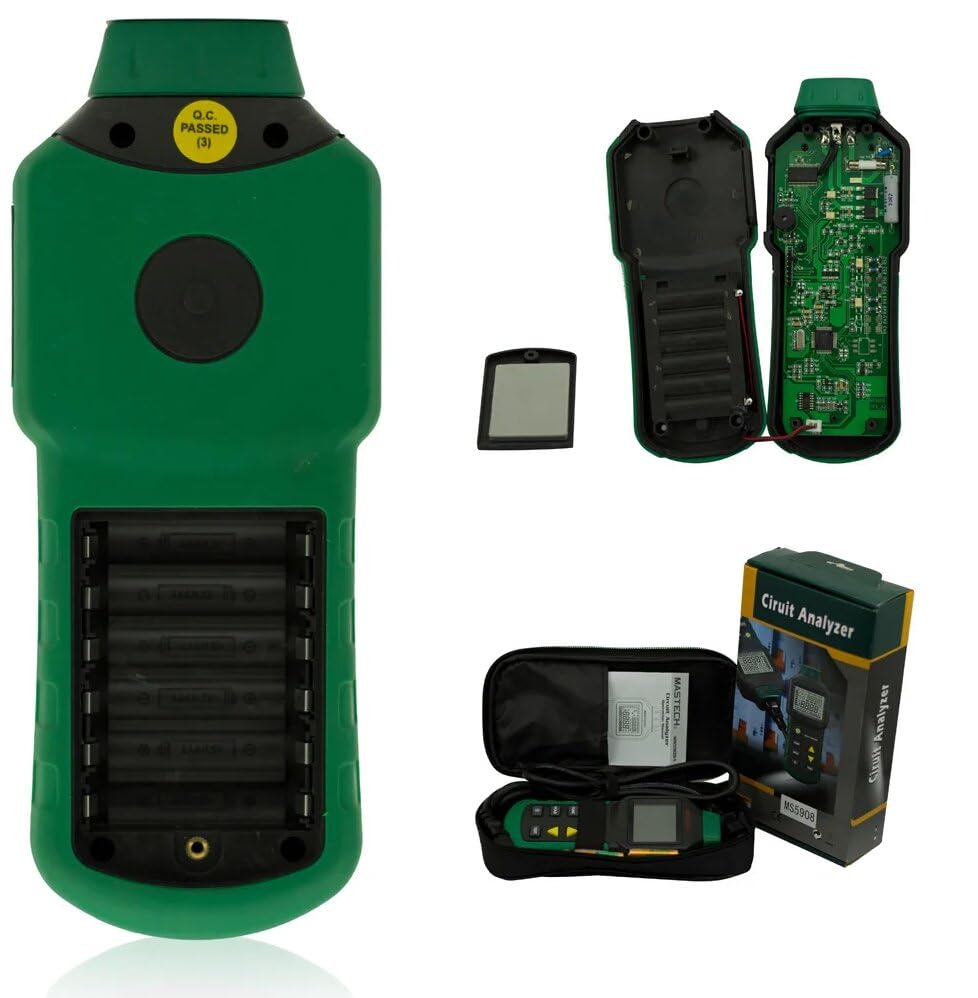
Figure 2: Contents of the Mastech MS5908A package, including the device, battery compartment, and carry case.

Figure 3: Diagram illustrating the packaging and included accessories for the MS5908A.
4. Setup
4.1 Battery Installation
- Locate the battery compartment on the back of the MS5908A unit.
- Open the battery compartment cover.
- Insert the 2 LR44 batteries, ensuring correct polarity (+ and -).
- Close the battery compartment cover securely.
4.2 Initial Power On
Press the power button (usually marked with a circle and vertical line) to turn on the device. The LCD display should illuminate.
5. Operating Instructions
The MS5908A offers various testing functions accessible via its control buttons. Familiarize yourself with the display and button layout.
5.1 General Operation
- Power Button: Turns the device ON/OFF.
- FUNC Button: Cycles through different measurement modes (e.g., Voltage, Frequency, Impedance).
- HOLD Button: Freezes the current reading on the display. Press again to release.
- Backlight Button: Toggles the display backlight ON/OFF for better visibility in low light conditions.
- TEST Button: Initiates specific tests like RCD or GFCI.
- Arrow Buttons (Up/Down): Used for navigation or adjusting parameters in certain modes.
5.2 Measuring AC Voltage (TRMS)
- Plug the MS5908A into the standard US wall socket (110V).
- Ensure the device is in AC Voltage measurement mode (use FUNC button if necessary).
- The display will show the True RMS AC Voltage reading.
5.3 Artificial Load Testing (Wire Drop Measurement)
The MS5908A (US plug version) supports artificial load testing at 12A, 15A, and 20A to measure wire drop.
- Plug the device into the circuit to be tested.
- Select the artificial load test mode using the FUNC button.
- Use the arrow buttons to select the desired load (12A, 15A, or 20A).
- Press the TEST button to initiate the load and measure the voltage drop.
5.4 Measuring Phase Voltage, Neutral Wire, Voltage to Earth, and Frequency
The device can analyze various aspects of the electrical supply:
- Plug the MS5908A into the socket.
- Cycle through the FUNC button to display readings for:
- Phase Voltage (Live to Neutral)
- Neutral Wire Voltage (Neutral to Earth)
- Voltage to Earth (Live to Earth)
- Frequency (Hz)
5.5 Measuring Phase (Live Wire), Neutral Wire, Earth Wire Conductor Impedance
- Plug the MS5908A into the socket.
- Select the impedance measurement mode using the FUNC button.
- The display will show the impedance values for Live, Neutral, and Earth conductors.
5.6 RCD (Residual Current Device) and GFCI (Ground Fault Circuit Interrupter) Testing
IMPORTANT: RCD/GFCI testing will trip the circuit breaker. Ensure all connected equipment is safely shut down or disconnected before performing this test.
- Plug the MS5908A into the RCD/GFCI protected socket.
- Select the RCD or GFCI test mode using the FUNC button.
- Press the TEST button. The device will simulate a fault condition.
- Observe if the RCD/GFCI trips within the specified time (e.g., 1ms~6.5S for RCD/GFCI Trip Time).
- The device will indicate if the test passed or failed.

Figure 4: The MS5908A Circuit Analyzer in use within a typical electrical testing environment.
6. Maintenance
- Cleaning: Wipe the device with a dry, soft cloth. Do not use abrasive cleaners or solvents.
- Storage: Store the device in a cool, dry place, away from direct sunlight and extreme temperatures. If storing for extended periods, remove the batteries to prevent leakage.
- Battery Replacement: Replace batteries when the low battery indicator appears on the display.
- Calibration: Regular calibration by qualified service personnel is recommended to ensure continued accuracy.
7. Troubleshooting
| Problem | Possible Cause | Solution |
|---|---|---|
| Device does not power on. | Dead or incorrectly installed batteries. | Check battery polarity or replace batteries. |
| Inaccurate readings. | Poor connection, incorrect mode, or device needs calibration. | Ensure secure connection. Verify correct measurement mode. Consider professional calibration. |
| Display is dim or flickering. | Low battery. | Replace batteries. |
| RCD/GFCI test does not trip the circuit. | Faulty RCD/GFCI, or incorrect test procedure. | Ensure the circuit is indeed RCD/GFCI protected. Re-read operating instructions for RCD/GFCI test. If issue persists, the RCD/GFCI itself may be faulty and require professional inspection. |
8. Specifications
The following table details the technical specifications for the Mastech MS5908A Circuit Analyzer:

Figure 5: Detailed specifications for the MS5908A, including ranges, resolutions, and accuracies.
| Feature | Detail |
|---|---|
| Model Number | GL-MS5908A |
| Power Source | Battery Powered (2 LR44 batteries included) |
| Product Dimensions | 6.3 x 3.54 x 1.97 inches (160 x 90 x 50 mm) |
| Item Weight | 1.1 Pounds (0.5 Kilograms) |
| Color | Green |
| Line Voltage (MS5908A) | 85~135V |
| Peak Line Voltage (MS5908A) | 120~190V |
| Line Frequency | 45~65Hz |
| Impedance (Live-Neutral & Earth) | 0.00~3.00Ω (Resolution 0.01Ω, Accuracy ±(2.5%+2)) |
| Neutral-Ground Voltage | 0.0~10.0V (Resolution 0.1V, Accuracy ±(2.5%+2)) |
| RCD Trip Current | 30mA~37mA (Resolution 0.1mA, Accuracy ±(1.0%+2)) |
| RCD Trip Time | 1ms~6.5S (Resolution 1mS, Accuracy ±(1.0%+2)) |
| GFCI Trip Current | 6mA~9mA (Resolution 0.1mA, Accuracy ±(1.0%+2)) |
| GFCI Trip Time | 1ms~6.5S (Resolution 1mS, Accuracy ±(1.0%+2)) |
| Voltage Drop Load Current | 12/15/20A |
| Auto Power Off | Yes |
| Data Hold | Yes |
| Low Battery Display | Yes |

Figure 6: Comparison of Mastech circuit analyzer models, including MS5908A and MS5908C.
9. Warranty and Support
Mastech products are designed for reliability and performance. For warranty information, technical support, or service inquiries, please refer to the contact information provided in the Quick Start Guide included with your product or visit the official Mastech website.
For general inquiries, you may also visit the Mastech Store on Amazon.


