1. Introduction
This manual provides detailed instructions for the safe and effective operation of your MASTECH MY74 Digital Multimeter. Please read this manual thoroughly before using the device and retain it for future reference. The MY74 is a compact, handheld digital multimeter designed for measuring AC/DC voltage, AC/DC current, resistance, capacitance, frequency, temperature, diode, continuity, and transistor hFE.
2. Safety Information
WARNING: To avoid electric shock or personal injury, read and understand all safety information before using this multimeter.
- Always ensure the multimeter is in good working condition and free from damage.
- Do not apply more than the rated voltage, as marked on the meter, between the terminals or between any terminal and earth ground.
- Use caution when working with voltages above 30V AC RMS, 42V peak, or 60V DC. These voltages pose a shock hazard.
- Always disconnect the test leads from the circuit before changing functions.
- Do not use the meter if the battery cover is not properly closed.
- Replace the battery as soon as the low battery indicator appears.
- Adhere to the measurement category (CAT III 600V) for safe operation.
3. Product Overview
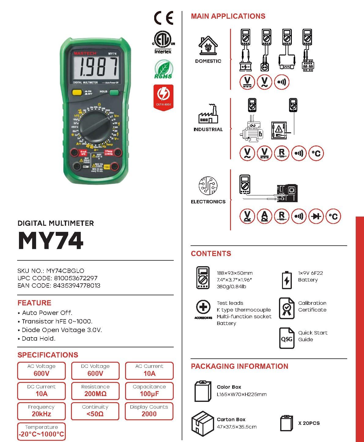
The MASTECH MY74 Digital Multimeter features a clear display, a rotary function switch, and input jacks for test leads. Familiarize yourself with the components shown below.

Key components include:
- LCD Display: Shows measurement readings, units, and function indicators.
- Rotary Function Switch: Selects the desired measurement function.
- ON/OFF Button: Powers the device on or off.
- HOLD Button: Freezes the current display reading.
- Input Jacks:
- COM: Common terminal for all measurements.
- VΩHz: Input for voltage, resistance, frequency, capacitance, diode, and continuity measurements.
- mAµA: Input for milliampere and microampere current measurements.
- 10A: Input for 10 Ampere current measurements.
4. Features
The MASTECH MY74 Digital Multimeter offers the following key features:
- Display: 2000 counts
- Auto Power Off function
- Transistor hFE measurement (0~1000)
- Diode Open Voltage: 3.0V
- Continuity Buzzer: Activates below 50Ω
- Data Hold function
- Low Battery Display indicator
5. Setup
5.1 Battery Installation
The MASTECH MY74 requires 2 LR44 batteries (included). To install or replace batteries:
- Ensure the multimeter is turned off and disconnect all test leads.
- Locate the battery compartment on the back of the meter.
- Unscrew the battery compartment cover.
- Insert the batteries, observing correct polarity (+ and -).
- Replace the battery compartment cover and secure it with the screw.
5.2 Connecting Test Leads
Always connect the black test lead to the COM jack. Connect the red test lead to the appropriate input jack based on the measurement function:
- VΩHz: For voltage, resistance, frequency, capacitance, diode, and continuity.
- mAµA: For current measurements up to 200mA.
- 10A: For current measurements up to 10A.
6. Operating Instructions
Before taking any measurement, ensure the test leads are correctly connected and the rotary switch is set to the desired function.
6.1 DC Voltage Measurement (V–)
- Connect the red test lead to the VΩHz jack and the black test lead to the COM jack.
- Set the rotary switch to the desired DC Voltage range (e.g., 200mV, 2V, 20V, 200V, 600V).
- Connect the test leads in parallel to the circuit or component under test.
- Read the voltage value on the display.
6.2 AC Voltage Measurement (V∼)
- Connect the red test lead to the VΩHz jack and the black test lead to the COM jack.
- Set the rotary switch to the desired AC Voltage range (e.g., 2V, 20V, 200V, 750V).
- Connect the test leads in parallel to the AC circuit or component.
- Read the voltage value on the display.
6.3 DC Current Measurement (A–)
CAUTION: Never connect the multimeter in parallel to a voltage source when measuring current. This can blow the fuse or damage the meter.
- Connect the black test lead to the COM jack.
- For currents up to 200mA, connect the red test lead to the mAµA jack. For currents up to 10A, connect the red test lead to the 10A jack.
- Set the rotary switch to the appropriate DC Current range (e.g., 2mA, 20mA, 200mA, 10A).
- Open the circuit and connect the multimeter in series with the load.
- Read the current value on the display.
6.4 AC Current Measurement (A∼)
CAUTION: Never connect the multimeter in parallel to a voltage source when measuring current. This can blow the fuse or damage the meter.
- Connect the black test lead to the COM jack.
- For currents up to 200mA, connect the red test lead to the mAµA jack. For currents up to 10A, connect the red test lead to the 10A jack.
- Set the rotary switch to the appropriate AC Current range (e.g., 2mA, 20mA, 200mA, 10A).
- Open the circuit and connect the multimeter in series with the load.
- Read the current value on the display.
6.5 Resistance Measurement (Ω)
CAUTION: Ensure the circuit is de-energized and all capacitors are discharged before measuring resistance.
- Connect the red test lead to the VΩHz jack and the black test lead to the COM jack.
- Set the rotary switch to the desired Resistance range (e.g., 200Ω, 2kΩ, 20kΩ, 200kΩ, 2MΩ, 200MΩ).
- Connect the test leads across the component to be measured.
- Read the resistance value on the display.
6.6 Diode Test (→|–)
- Connect the red test lead to the VΩHz jack and the black test lead to the COM jack.
- Set the rotary switch to the Diode Test position.
- Connect the red test lead to the anode and the black test lead to the cathode of the diode.
- The display will show the forward voltage drop. Reverse the leads; the display should show "OL" (Open Loop) for a good diode.
6.7 Continuity Test (♫)
- Connect the red test lead to the VΩHz jack and the black test lead to the COM jack.
- Set the rotary switch to the Continuity Test position.
- Connect the test leads across the circuit or component.
- If the resistance is less than approximately 50Ω, the buzzer will sound, indicating continuity.
6.8 Transistor hFE Test
- Set the rotary switch to the hFE position.
- Insert the transistor's Emitter, Base, and Collector leads into the corresponding holes in the multi-function socket (NPN or PNP).
- Read the hFE value on the display.
6.9 Capacitance Measurement (F)
CAUTION: Ensure the capacitor is fully discharged before measuring capacitance to avoid damage to the meter.
- Connect the red test lead to the VΩHz jack and the black test lead to the COM jack.
- Set the rotary switch to the Capacitance range (e.g., 2nF, 20nF, 200nF, 2µF, 20µF, 100µF).
- Connect the test leads across the capacitor.
- Read the capacitance value on the display.
6.10 Frequency Measurement (Hz)
- Connect the red test lead to the VΩHz jack and the black test lead to the COM jack.
- Set the rotary switch to the Frequency range (20kHz).
- Connect the test leads in parallel to the signal source.
- Read the frequency value on the display.
6.11 Temperature Measurement (°C/°F)
- Connect the K-type thermocouple to the VΩHz and COM jacks, observing polarity.
- Set the rotary switch to the Temperature range.
- Place the thermocouple probe at the point where temperature is to be measured.
- Read the temperature value on the display.
7. Maintenance
7.1 Cleaning
Wipe the case with a damp cloth and mild detergent. Do not use abrasives or solvents. Ensure the meter is completely dry before use.
7.2 Battery Replacement
Refer to section 5.1 for battery replacement instructions. Replace batteries promptly when the low battery indicator appears to ensure accurate readings.
7.3 Fuse Replacement
If the current measurement function fails, the fuse may need replacement. Refer to the specifications for the correct fuse type and rating. Fuse replacement should only be performed by qualified personnel.
8. Troubleshooting
| Problem | Possible Cause | Solution |
|---|---|---|
| Meter does not power on. | Dead or incorrectly installed batteries. | Check battery polarity or replace batteries. |
| "OL" (Overload) displayed. | Measurement exceeds selected range or open circuit. | Select a higher range or check for open circuit. |
| Incorrect current reading. | Blown fuse or incorrect input jack. | Check fuse and ensure test lead is in the correct current input jack (mAµA or 10A). |
| No continuity beep. | Resistance is too high or circuit is open. | Check the circuit for breaks. Ensure resistance is below 50Ω. |
9. Specifications
The following table details the technical specifications for the MASTECH MY74 Digital Multimeter.

| Function | Range | Resolution | Accuracy |
|---|---|---|---|
| DC Voltage | 200mV/2V/20V/200V | 0.1mV/1mV/10mV/0.1V | ±(0.5%+2) |
| 600V | 1V | ±(0.8%+2) | |
| AC Voltage | 2V/20V/200V | 1mV/10mV/100mV | ±(0.8%+3) |
| 750V | 1V | ±(1.2%+3) | |
| DC Current | 2mA | 1µA | ±(0.8%+1) |
| 20mA | 10µA | ±(1.5%+1) | |
| 200mA | 0.1mA | ±(1.5%+1) | |
| 10A | 10mA | ±(2.0%+5) | |
| AC Current | 20mA | 10µA | ±(1.0%+5) |
| 200mA | 0.1mA | ±(1.8%+5) | |
| 10A | 0.01A | ±(3.0%+7) | |
| Resistance | 200Ω | 0.1Ω | ±(0.8%+3) |
| 2kΩ/20kΩ/200kΩ/2MΩ | 1Ω/10Ω/100Ω/1kΩ | ±(0.8%+2) | |
| 20MΩ | 10kΩ | ±(1.0%+2) | |
| 200MΩ | 0.1MΩ | ±(6.0%+10) | |
| Diode Open Voltage | 3.0V | N/A | N/A |
| Capacitance | 2nF/20nF/200nF/2µF | 1pF/10pF/0.1nF/1nF | ±(4.0%+3) |
| 20µF | 10nF | ±(5.0%+3) | |
| 100µF | 0.1µF | ±(6.0%+10) | |
| Frequency | 20kHz | 0.01kHz | ±(2.0%+5) |
| Temperature | -20°C~0°C | 1°C | ±(5.0%+4) |
| 1°C~400°C | 1°C | ±(2.0%+3) | |
| 401°C~1000°C | 1°C | ±(2.0%+5) | |
| Transistor hFE | 0~1000 | N/A | N/A |
| Display | 2000 counts | ||
| Auto Power Off | Yes | ||
| Continuity Buzzer | <50Ω | ||
| Data Hold | Yes | ||
| Low Battery Display | Yes | ||
| Power Source | 2 LR44 batteries (included) | ||
| Product Dimensions | 16 x 9 x 5 cm | ||
| Item Weight | 0.5 Kilograms | ||
| Safety Rating | CAT III 600V, CE, RoHS | ||
Note: Accuracy specifications are given for one year after calibration, at 18°C to 28°C (64°F to 82°F), with relative humidity up to 75%.
10. Warranty and Support
MASTECH products are designed for reliability and performance. For warranty information and technical support, please refer to the documentation included with your purchase or visit the official MASTECH website. The EU Spare Part Availability Duration is 1 year.


