
1. Introduction
This manual provides essential information for the proper setup, operation, and maintenance of your FOSA ATU-100 Mini Automatic Antenna Tuner. Designed for ham radio enthusiasts, the ATU-100 offers automatic antenna tuning across a wide frequency range, ensuring efficient signal transmission.
2. Product Overview
2.1 Key Features
- Automatic Tuning: Tunes antennas automatically without external control wires.
- Wide Frequency Range: Operates from 1.8 MHz to 55 MHz.
- Compact Design: Features a durable, lightweight aluminum alloy metal shell.
- OLED Display: Equipped with a 0.96-inch OLED display for clear status indication.
- Power Options: Available with a Type-C charging port for internal battery (1350mAh) or external 12V DC power.
- High-Quality Components: Utilizes 1000V high voltage SMD capacitors and advanced PIC chips.
- UHF Connectors: Standard UHF (SO-239) connectors for radio and antenna connections.
2.2 Components
The ATU-100 package typically includes the ATU-100 tuner unit and a USB Type-C charging cable (for models with internal battery) or a DC power cable with bare leads (for models requiring external power). Ensure all components are present upon unboxing.

Figure 1: ATU-100 tuner unit and included USB cable.

Figure 2: Front view of the ATU-100, highlighting the 0.96-inch OLED display and Type-C charging port.

Figure 3: Rear panel of the ATU-100, showing the ANT (Antenna) and RFIN (Radio Input) UHF connectors.
3. Specifications
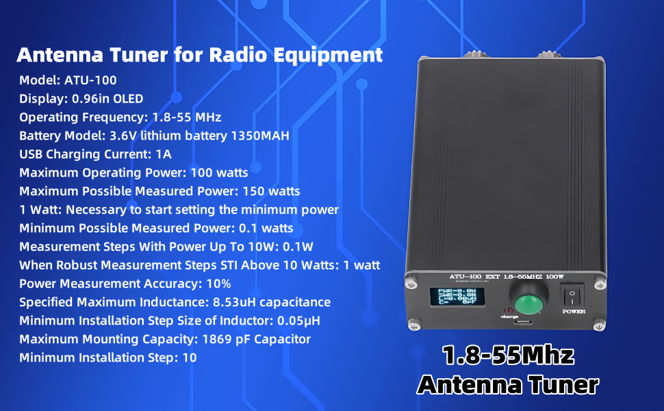
Figure 4: Visual representation of ATU-100 specifications.
| Specification | Value |
|---|---|
| Model | ATU-100 |
| Operating Frequency | 1.8 - 55 MHz |
| Display | 0.96 inch OLED |
| Battery Model (if applicable) | 3.6V lithium battery 1350MAH |
| USB Charging Current | 1A |
| Maximum Operating Power | 100 watts |
| Maximum Possible Measured Power | 150 watts |
| Minimum Power for Tuning | 1 watt |
| Minimum Possible Measured Power | 0.1 watts |
| Measurement Steps (up to 10W) | 0.1W |
| Measurement Steps (above 10W) | 1 watt |
| Power Measurement Accuracy | 10% |
| Specified Maximum Inductance | 8.53uH |
| Minimum Inductor Step Size | 0.05μH |
| Maximum Mounting Capacity | 1869 pF |
| Minimum Installation Step | 10 |
| Product Dimensions | 8.27 x 5.12 x 2.36 inches |
| Item Weight | 1.03 pounds |
| Housing Material | Aluminum Alloy |
4. Setup and Installation
4.1 Connecting the Tuner
- Connect your radio's antenna output to the IN (RFIN) UHF connector on the ATU-100 using a suitable coaxial cable.
- Connect your antenna to the ANT UHF connector on the ATU-100 using a suitable coaxial cable.
- For long wire antennas, connect the antenna wire to the red terminal and a ground wire to the black terminal (GND) on the rear panel.
4.2 Powering the ATU-100
The ATU-100 requires a 9-12V DC power source to operate. Ensure your power supply can provide at least 0.5A. For models with an internal battery, the Type-C port can be used for charging.
- External Power: Connect a 9-12V DC power supply to the DC input jack on the rear panel. Ensure correct polarity.
- Internal Battery (if applicable): Charge the internal 1350mAh lithium battery via the Type-C USB port. A red indicator light will show charging status.

Figure 5: Important notes on power requirements and tuning recommendations.
4.3 Power Considerations
- It is recommended to use a 9-12V power source to start the ATU-100. Power banks or computer USB ports may not provide sufficient voltage for initial startup.
- The tuner typically draws about 0.5A of 12V DC.
Video 1: Overview of the ATU-100 Mini Automatic Antenna Tuner, including physical features and basic connections.
Video 2: Detailed comparison and demonstration of ATU-100 models, including battery and non-battery versions, power connections, and operational differences.
5. Operating Instructions
5.1 Powering On/Off
To power on the ATU-100, toggle the POWER switch to the ON position. The OLED display will illuminate, showing current power, SWR, inductance (L), and capacitance (C) values. To power off, toggle the POWER switch to the OFF position.
5.2 Tuning Process
The ATU-100 can operate in automatic or manual tuning modes. The mode selection button is typically located on the rear panel (for some models) or integrated into the front panel controls.
- Automatic Tuning: With the tuner powered on, transmit a low-power signal (minimum 1 watt, recommended not to exceed 30 watts during tuning) from your radio. The ATU-100 will automatically detect the signal and begin the tuning process, adjusting inductance and capacitance to achieve the lowest possible SWR.
- Manual Tuning: Press the TUNE button on the front panel while transmitting a low-power signal. The tuner will initiate a tuning cycle.
- Reset Tuning: To clear previous tuning settings, press the TUNE button twice rapidly. The display will briefly show 'RESET'.
5.3 Display Information
The 0.96-inch OLED display provides real-time information during operation:
- PWR: Transmitted power in watts.
- SWR: Standing Wave Ratio.
- L: Inductance value in microHenries (uH).
- C: Capacitance value in picoFarads (pF).
- EFF: Efficiency percentage.
5.4 Bypass Mode
Some ATU-100 models feature a BYPASS button. Pressing this button will bypass the tuning circuit, allowing the signal to pass directly through the tuner without modification. This can be useful if your antenna is already perfectly matched for the operating frequency or if you wish to use the tuner as a simple wattmeter.
Video 3: Short demonstration of the ATU-100's automatic tuning function.
6. Important Considerations
- Minimum Power: Insufficient adjustment may occur if the transmitted power is below 5 watts. Avoid operating below 5 watts during tuning.
- Maximum Tuning Power: It is recommended that the maximum power should not exceed 30 watts during the tuning process. The tuner can handle up to 100 watts after tuning is complete. Exceeding 30 watts during tuning may damage the unit.
- Voltage for Startup: A 9-12V power source is required to start the ATU-100. Using a power bank or computer USB port for initial startup may not provide adequate voltage.
7. Maintenance
- Keep the tuner clean and free from dust and moisture.
- Store the unit in a dry environment when not in use.
- Avoid dropping or subjecting the tuner to strong impacts.
8. Troubleshooting
- Tuner not powering on: Verify that the power source is providing 9-12V DC and is correctly connected. For battery models, ensure the internal battery is charged.
- High SWR after tuning: Ensure all antenna and radio connections are secure. Check the antenna for any faults or damage. Try resetting the tuner and re-tuning.
- Tuner not responding: Power cycle the unit. If the issue persists, ensure the power supply meets the specified voltage and current requirements.
9. Warranty and Support
For warranty information or technical support, please refer to the product's packaging or contact FOSA customer service directly. Keep your purchase receipt for any warranty claims.