1. Introduction
This manual provides comprehensive instructions for the installation, operation, and maintenance of the Temank MPPT 60A-Parallel Solar Charge Controller. This device is designed to efficiently manage power flow from solar panels to batteries, ensuring optimal charging and system performance. It supports various battery types and offers advanced features for enhanced energy management.

Figure 1: Temank MPPT 60A-Parallel Solar Charge Controller with LCD display.
2. Safety Instructions
- Ensure all wiring is performed by qualified personnel in accordance with local electrical codes.
- Always disconnect power from solar panels and batteries before installation or maintenance.
- Wear appropriate personal protective equipment (PPE), including insulated gloves and eye protection.
- Do not attempt to disassemble or repair the controller. Refer to qualified service personnel.
- Install the controller in a well-ventilated area, away from flammable materials and direct sunlight.
- Ensure proper grounding of the system.
3. Product Overview
3.1 Key Features
- Maximum 12 Units in Parallel: Allows for expansion of solar system capacity and improved overall power output, suitable for large solar systems.
- Dual Cooling, Efficient Heat Dissipation: Constructed with die-cast aluminum and features a silent intelligent bladeless fan for effective cooling (activates >45°C, turns off <40°C).
- Compatible with Multiple Battery Types: Supports 12V/24V/36V/48V lead-acid (Sealed, Gel, Flooded) and Lithium (LFP) batteries. User-customizable charging parameters.
- Wide Range Voltage/Power Support: Supports high PV input power/voltage. For 12V systems, suggested solar power is 720W (DC20V~DC80V); for 24V, 1440W (37~105V); for 36V, 2100W (50~160V); for 48V, 2800W (72-160V).
- 99% Tracking Technology: Advanced Maximum Power Point Tracking (MPPT) technology ensures continuous tracking of the array’s maximum power point for optimal battery charging, with tracking efficiency not less than 98.1% and peak conversion efficiency up to 97%.
- Negative Grounding Design: Enhances safety.

Figure 2: Overview of MPPT 60A Solar Controller features including voltage support and cooling.
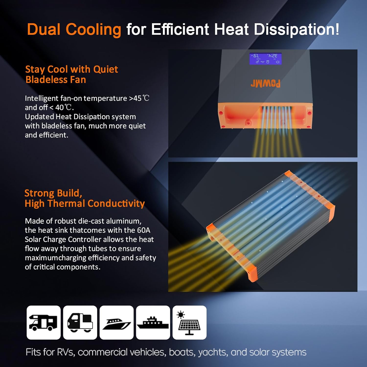
Figure 3: Illustration of the dual cooling system with die-cast aluminum and bladeless fan for efficient heat dissipation.

Figure 4: The controller is compatible with various battery types including GEL, FLD, SLA, LI (LiFePO4), and user-defined settings.
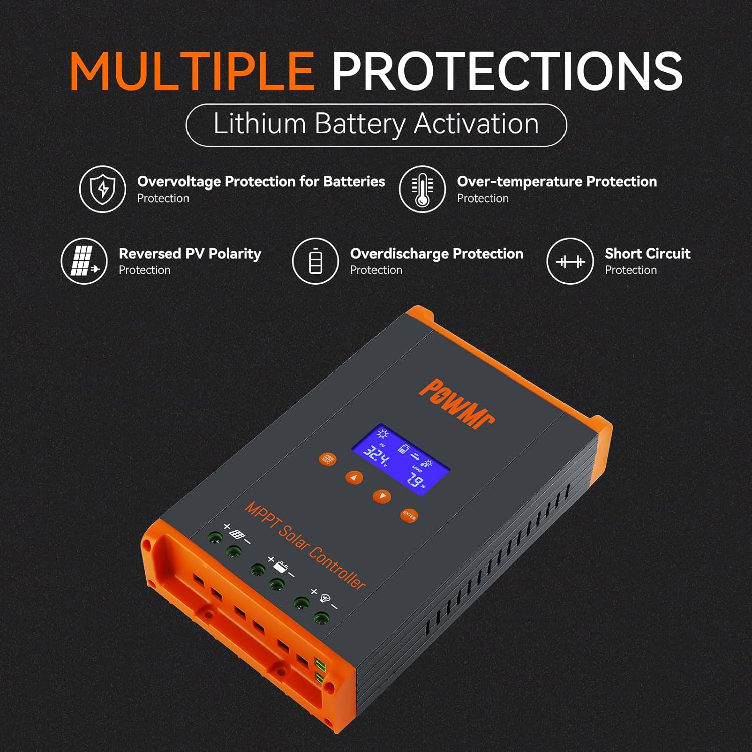
Figure 5: The controller includes multiple protection features such as overvoltage, over-temperature, reversed PV polarity, overdischarge, and short circuit protection.
4. Setup and Installation
4.1 Mounting the Controller
Securely mount the controller on a wall using four screws. Ensure adequate clearance around the controller for proper airflow and heat dissipation. A minimum of 75mm (approximately 3 inches) clearance is recommended on the top, bottom, left, and right sides.

Figure 6: Recommended mounting clearances (75mm on all sides) for optimal air circulation and heat dissipation.
4.2 Wiring Connections
Follow the wiring diagrams carefully. Loosen the terminal screws before inserting wires, then tighten them securely. Recommended wire size: 9AWG.
- Connect the battery wires first (positive and negative).
- Connect the solar input wires (positive and negative).
- Connect the DC load wires (positive and negative).

Figure 7: Detailed diagrams for single controller connection and parallel operation schematic, showing battery, solar array, and load connections.
4.3 Parallel Operation Setup
For parallel operation, multiple controllers can be connected to the same battery bank. Each controller should have individual connections to separate photovoltaic arrays. Communication lines must be configured between controllers for proper synchronization.

Figure 8: Comparison of power reception with one MPPT vs. two MPPTs in parallel operation, demonstrating increased electricity generation.
Video 1: HHJ60-PRO Paralleling Guide. This video demonstrates the physical installation and wiring for parallel operation of multiple controllers.
5. Operating Instructions
5.1 Display Interface
After startup, the controller's LCD display shows various parameters. Use the "Up" and "Down" buttons to navigate through the main loop interfaces:
- Interface 1: Solar input voltage (PV) and load power consumption (LOAD).
- Interface 2: Battery voltage (BATT) and charging current (CHARGE).
- Interface 3: Operating mode and device temperature (TEMP).
- Interface 4: Fault codes (FAULT) and parallel operation code.
Video 2: HHJ60-PRO Complete Operating Guide. This video provides a detailed walkthrough of the controller's display interfaces and settings.
5.2 Parameter Settings
Press the "PRG/ESC" button to enter the settings interface loop. Use "Up" and "Down" to navigate and "ENTER" to confirm changes.
- d00 (Load Operating Mode):
- 24H: Load is continuously on.
- 00H: Light control mode (load output determined by sufficient solar energy).
- 1H to 23H: Timed light-on and constant-off mode (load output activated upon detecting photovoltaic input and remains on for the set duration).
- d01 (Charging Voltage): Configures the voltage the controller maintains after the battery completes the boost charging stage.
- d02 (Boost Charging Voltage): Sets the charging voltage during the boost charging stage.
- d03 (Low Voltage Protection): Sets the low voltage protection voltage of the battery.
- d04 (Battery Voltage Calibration): Used to calibrate the battery voltage value displayed by the controller. If the displayed value differs from a multimeter reading at the battery port, use this program to calibrate.
- d05 (Parallel Communication Code): Configures the communication address of the controller in parallel operation. The controller with the lowest communication code acts as the master. If the main controller (code 1) fails, functions will cascade to the next valid operating controller.
- d06 (Battery Type Setting): Sets the battery type with options including sealed lead-acid batteries, gel-sealed lead-acid batteries, flooded lead-acid batteries, 4-string lithium iron phosphate batteries, 8-string lithium iron phosphate batteries, 15-string lithium iron phosphate batteries, 16-string lithium iron phosphate batteries, and custom options ("USE"). Choosing "USE" allows manual settings for "d01", "d02", and "d03".
- d07 (System Voltage Configuration): Configures the system voltage.
After completing the settings, press the "ESC" key to exit and return to the main page.

Figure 9: Illustration of the MPPT three-stage charging mode: Boost Charge, Constant Charging, and Float Charge, designed to prolong battery lifecycle.
6. Maintenance
- Regularly inspect all wiring connections for tightness and corrosion.
- Keep the controller clean and free from dust and debris to ensure proper heat dissipation.
- Check the fan for obstructions and ensure it operates correctly when activated.
- Monitor the display for any fault codes and address them promptly.
7. Troubleshooting
If the controller is not functioning as expected, consider the following:
- No Display/Power: Check battery connections and ensure the circuit breaker is on.
- No Charging: Verify solar panel connections and ensure sufficient sunlight. Check for any fault codes on the display.
- Overheating: Ensure adequate ventilation and clearance around the controller. Clean any dust or debris from the cooling fins.
- Incorrect Readings: Calibrate battery voltage using the d04 setting if necessary.
- For persistent issues, refer to the detailed troubleshooting section in the full product manual or contact customer support.
8. Specifications
| Attribute | Value |
|---|---|
| Manufacturer | Temank |
| Charging Port Type | Serial |
| Package Dimensions | 9.96 x 7.17 x 2.83 inches |
| Item Weight | 2.81 pounds |
| Country of Origin | China |
| Batteries required | No |
| Included Components | solar controller |
| Color | Orange |
| Brand | Temank |
| Voltage | 35 Volts (DC) |
| Display Type | LCD |
| Operating Temperature | 45 Degrees Celsius |
9. Warranty and Support
For warranty information, technical support, or service inquiries, please refer to the contact details provided with your product packaging or visit the official Temank website. Keep your purchase receipt for warranty claims.


