
1. Introduction
The VIHELM PM1508 is a high-precision digital insulation resistance tester designed for accurate measurement of insulation resistance, AC/DC voltage, frequency, and continuity. This compact and functional device features a clear LCD display, multiple test voltages, and functions such as ZERO, HOLD, LOCK, PI/DAR, and backlight. It is suitable for various electrical testing applications requiring reliable insulation resistance measurements up to 100 Gigaohms.
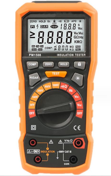
Figure 1: VIHELM PM1508 Insulation Resistance Tester. This image shows the front view of the orange and black meter with its digital display and rotary dial.
2. Safety Information
To ensure safe operation and prevent damage to the meter, please read and follow all safety instructions carefully. This manual contains information and warnings that must be observed to ensure safe operation and keep the meter in safe operating condition.
- Always adhere to local and national safety codes.
- Do not use the meter if it appears damaged or if the insulation on the test leads is compromised.
- Ensure the battery compartment is securely closed before operation.
- Do not apply voltage exceeding the maximum rated voltage marked on the meter.
- Use caution when working with voltages above 30V AC RMS, 42V peak, or 60V DC. These voltages pose a shock hazard.
- Always disconnect power to the circuit under test before making insulation resistance measurements.
- Discharge all capacitive circuits after testing.
- Do not operate the meter in explosive gas, vapor, or dust environments.
- Replace batteries when the low battery indicator appears to ensure accurate readings.
- Refer to the specifications section for the meter's safety rating (CAT III 600V).
3. Product Overview
3.1. Components
The VIHELM PM1508 comes with the following components:
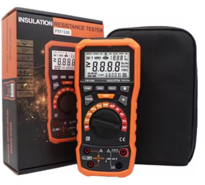
Figure 2: Package Contents. This image displays the PM1508 meter, test leads, alligator clips, a cloth bag, and a user manual.
- VIHELM PM1508 Insulation Resistance Tester
- Test Leads
- Alligator Clips
- Cloth Bag
- User Manual (this document)
- Color Box (packaging)
3.2. Meter Layout and Controls
Familiarize yourself with the various parts of the meter before operation.
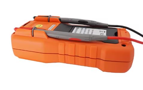
Figure 3: Operation Panel Diagram. This image highlights key features including the LCD display area, Zeroing button, HOLD button, LOCK function, Backlight button, TEST button, Function position selection dial, Polarization Index/Dielectric Absorption Ratio button, Compare function, and Input ports.
- LCD Display Area: Shows measurement readings, units, and status indicators.
- ZERO Button: Used for zeroing measurements.
- HOLD Button: Enters/exits the reading hold mode.
- LOCK Function: Activates the LOCK function for continuous testing.
- Backlight Button: Turns the LCD backlight on/off.
- TEST Button: Starts/ends the test.
- Function Position Selection Dial: Selects the desired measurement function (OFF, VDC, VAC, Hz, Ω, 50V, 100V, 250V, 500V, 1000V).
- PI/DAR Button: Selects Polarization Index or Dielectric Absorption Ratio measurement.
- COMP Button: Activates the Compare function.
- Input Ports: Terminals for connecting test leads.
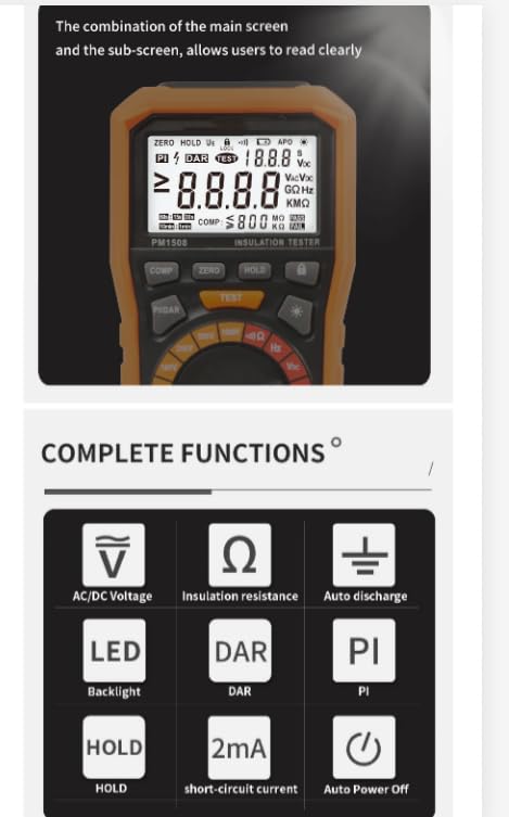
Figure 4: Clear LCD Display. This image illustrates the main and sub-screen display, designed for clear readability of measurement results and indicators.
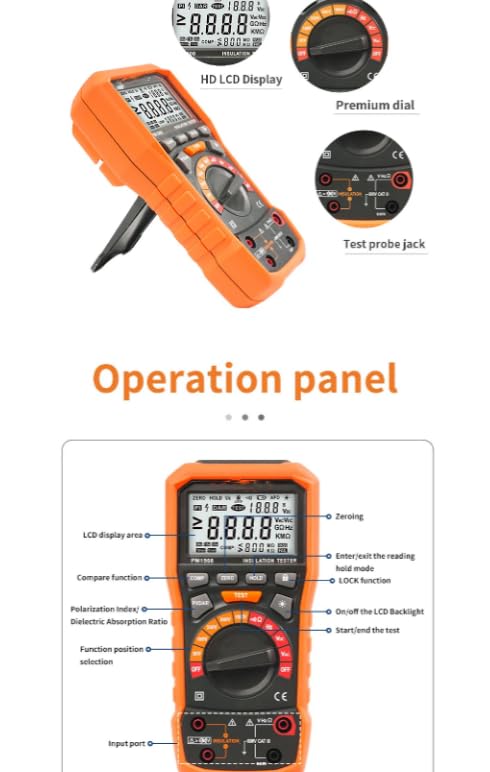
Figure 5: Angled view of the PM1508, highlighting the HD LCD display, the premium rotary dial for function selection, and the test probe jacks at the bottom.
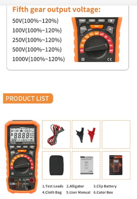
Figure 6: Side view of the PM1508, showing the robust casing and connected test leads.
4. Setup
4.1. Battery Installation
The PM1508 is powered by 4 x 1.5V AA batteries. To install or replace batteries:
- Ensure the meter is turned OFF.
- Locate the battery compartment cover on the back of the meter.
- Use a screwdriver to open the battery compartment.
- Insert four 1.5V AA batteries, observing the correct polarity (+/-).
- Replace the battery compartment cover and secure it with the screw.
Note: Replace batteries immediately when the low battery indicator appears on the display to ensure accurate measurements.
4.2. Connecting Test Leads
Connect the red test lead to the “VΩ” input terminal and the black test lead to the “COM” input terminal for most measurements. For specific tests, refer to the relevant operating instructions.
5. Operating Instructions
5.1. Powering On/Off
Turn the rotary dial from the “OFF” position to any desired function to power on the meter. To power off, turn the rotary dial back to the “OFF” position.
5.2. Function Selection
Rotate the central dial to select the desired measurement function. Available functions include:
- VDC: DC Voltage Measurement
- VAC: AC Voltage Measurement
- Hz: Frequency Measurement
- Ω: Low Resistance, Continuity, Diode Test
- 50V, 100V, 250V, 500V, 1000V: Insulation Resistance Test Voltages
5.3. Insulation Resistance Measurement
This function measures the insulation resistance of electrical systems and components.
- Ensure the circuit under test is de-energized and safely discharged.
- Turn the rotary dial to the desired insulation test voltage (50V, 100V, 250V, 500V, or 1000V).
- Connect the test leads to the circuit or component under test.
- Press the TEST button to start the measurement. The test voltage will be applied.
- Read the insulation resistance value on the LCD display.
- Press the TEST button again to stop the measurement and discharge the circuit.
The meter offers five output voltage options for insulation testing:
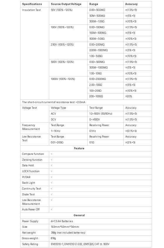
Figure 7: Available Output Voltages. This image lists the five selectable output voltages for insulation resistance testing: 50V, 100V, 250V, 500V, and 1000V, each with a tolerance range of 100%~120%.
5.4. Voltage Measurement (ACV/DCV)
To measure AC or DC voltage:
- Turn the rotary dial to “VDC” for DC voltage or “VAC” for AC voltage.
- Connect the test leads in parallel to the circuit or component.
- Read the voltage value on the display.
5.5. Frequency Measurement (Hz)
To measure frequency:
- Turn the rotary dial to “Hz”.
- Connect the test leads to the circuit where frequency needs to be measured.
- Read the frequency value on the display.
5.6. Low Resistance, Continuity, and Diode Test
Turn the rotary dial to “Ω” for these functions. Use the function button (if available, or cycle through modes) to select between low resistance, continuity, or diode test.
- Low Resistance: Measures resistance values.
- Continuity: An audible beep indicates a continuous circuit (low resistance).
- Diode Test: Measures the forward voltage drop of a diode.
5.7. Polarization Index (PI) and Dielectric Absorption Ratio (DAR)
These tests are used to assess the quality of insulation over time. Press the PI/DAR button to initiate these measurements after selecting an insulation test voltage.
- DAR: Ratio of insulation resistance measured at 60 seconds to that measured at 30 seconds.
- PI: Ratio of insulation resistance measured at 10 minutes to that measured at 1 minute.
5.8. Special Functions
- ZERO Function: Press the ZERO button to compensate for test lead resistance in low resistance measurements.
- HOLD Function: Press the HOLD button to freeze the current reading on the display. Press again to release.
- LOCK Function: Press the LOCK button during an insulation test to maintain the test voltage without continuously holding the TEST button. Press again to release.
- Backlight: Press the backlight button to illuminate the display for use in dimly lit environments. Press again to turn off.
- Auto Power Off (APO): The meter will automatically power off after a period of inactivity to conserve battery life.
- COMPARE Function: Allows setting a reference value for comparison during measurements.
6. Specifications
The following table details the technical specifications of the VIHELM PM1508 Insulation Resistance Tester.
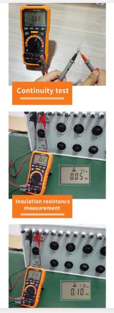
Figure 8: Technical Specifications. This image provides a comprehensive table of the PM1508's specifications, including insulation test ranges, voltage test, frequency, low resistance, features, and general information.
| Category | Parameter | Value / Range | Accuracy |
|---|---|---|---|
| Insulation Test | Source Output Voltage | 50V (100%~120%) | 0.00-500MΩ: ±(5%+5) 50M-500MΩ: ±(1.5%+5) 500M-1.0GΩ: ±(10%+5) |
| Source Output Voltage | 100V (100%~120%) | 0.00-500MΩ: ±(5%+5) 50M-500MΩ: ±(1.5%+5) 500M-5.0GΩ: ±(10%+5) | |
| Source Output Voltage | 250V (100%~120%) | 0.00-200MΩ: ±(5%+5) 200M-1000MΩ: ±(1.5%+5) 1.0G-5.0GΩ: ±(10%+5) | |
| Source Output Voltage | 500V (100%~120%) | 0.00-500MΩ: ±(5%+5) 500M-1000MΩ: ±(1.5%+5) 1.0G-10GΩ: ±(10%+5) | |
| Source Output Voltage | 1000V (100%~120%) | 0.00-2000MΩ: ±(5%+5) 2.0G-10GΩ: ±(1.5%+5) 10G-20GΩ: ±(10%+5) 20G-100GΩ: ±20% | |
| Short-circuit current of resistance test | <2.0mA | ||
| Voltage Test | Voltage Type | 1.0-600V (50/60Hz) | ±(1.5%+5) |
| DCV | 0-600V | ±(1.5%+5) | |
| Frequency Measurement | Test Range | 1-1KHz | ±(0.1%+3) |
| Resolving Power | 0.1Hz | ||
| Low Resistance Test | Test Range | 0.01-200Ω | ±(2%+5) |
| Resolving Power | 0.01Ω | ||
| Features | |||
| Compare function | ✓ | ||
| Zeroing function | ✓ | ||
| Data Hold | ✓ | ||
| LOCK function | ✓ | ||
| PI/DAR | ✓ | ||
| Back Light | ✓ | ||
| Continuity Test | ✓ | ||
| Diode Test | ✓ | ||
| Low Resistance Measurement | ✓ | ||
| Auto Power Off | ✓ | ||
| General | |||
| Power Supply | 4 × 1.5 AA Batteries | ||
| Size | 193mm × 63mm × 54mm | ||
| Net weight | 398g (not included batteries) | ||
| Gross weight | 818g | ||
| Safety Rating | EN61010-1, EN61010-2-032, EN61326, CAT III 600V | ||
7. Maintenance
7.1. Cleaning
Wipe the meter's casing with a damp cloth and mild detergent. Do not use abrasives or solvents. Ensure the meter is completely dry before use.
7.2. Battery Replacement
Refer to Section 4.1 for battery installation and replacement instructions. Always use new 1.5V AA batteries. Remove batteries if the meter is not used for an extended period to prevent leakage.
7.3. Storage
Store the meter in a cool, dry place, away from direct sunlight and extreme temperatures. If storing for a long time, remove the batteries.
8. Troubleshooting
This section addresses common issues you might encounter with the PM1508.
| Problem | Possible Cause | Solution |
|---|---|---|
| Meter does not power on. | Dead or incorrectly installed batteries. | Check battery polarity and replace batteries if necessary. |
| Inaccurate readings. | Low battery, dirty test leads, incorrect function selected, external interference. | Replace batteries, clean test leads, ensure correct function is selected, move away from strong electromagnetic fields. |
| No display or partial display. | Battery issue, internal fault. | Check/replace batteries. If problem persists, contact customer support. |
| "OL" or "OVER" displayed. | Measurement exceeds the meter's range. | Ensure the measurement is within the specified range for the selected function. |
9. Warranty and Support
VIHELM products are manufactured to high quality standards. For warranty information, technical support, or service inquiries, please refer to the warranty card included with your product or contact your local distributor. Please retain your proof of purchase for warranty claims.
For further assistance, please visit the official VIHELM website or contact their customer service department.