
SPEEDY BEE F405 V4 60A Flight Controller Stack
SpeedyBee F405 V4 60A Flight Controller Stack User Manual
Model: F405 V4 60A
1. Product Overview
The SpeedyBee F405 V4 60A Flight Controller Stack is a high-performance system designed for FPV drones, integrating a powerful F405 Flight Controller and a 4-in-1 60A Electronic Speed Controller (ESC). This stack features wireless Betaflight configuration via Bluetooth, an onboard barometer, and a blackbox for flight data recording. It is engineered for robust performance and ease of use, providing a smooth and reliable flight experience.
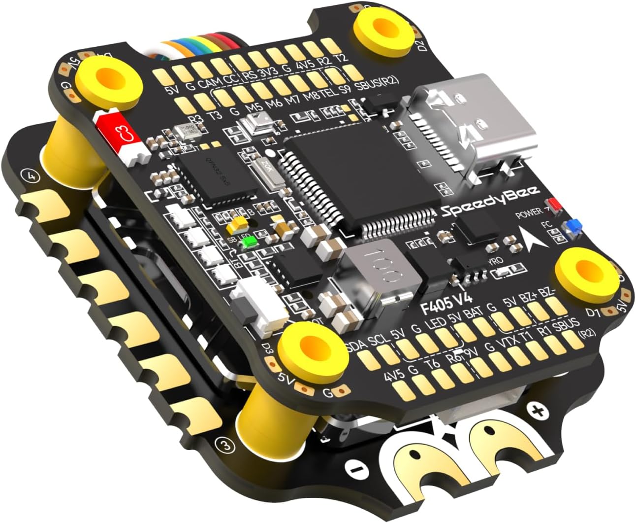
Image: SpeedyBee F405 V4 60A Flight Controller Stack, showing the stacked flight controller and ESC boards.

Image: Overview of SpeedyBee F405 V4 BLS 60A Stack features, highlighting wireless configuration, 60A ESC, dual gyroscope power supply filtering, onboard battery indicator, 8 motor support, LED pads, BECs, fixed SD card compatibility, wireless motor direction change, 1000uF capacitor, DJI Air Unit Plug & Play, and built-in barometer.
2. Package Contents
Verify that all items listed below are included in your package:

Image: Diagram showing all components included in the SpeedyBee F405 V4 60A Stack package.
- SpeedyBee F405 V4 Flight Controller x 1
- SpeedyBee BLS 60A 4-in-1 ESC x 1
- 35V 1000uF Low ESR Capacitor x 1
- M3 Nylon Nut x 5
- M3 Silicone O Ring x 5
- M3*8mm Silicone Grommets (for FC) x 1
- M3*8.1mm Silicone Grommets (for ESC) x 1
- SH 1.0mm 25mm-length 8pin Cable (for FC-ESC connection) x 1
- SH 1.0mm 75mm-length 8pin Cable x 1
- M3*30mm Inner-hexagon Screws x 5
- DJI 6pin Cable (80mm) x 1
- XT60 Power Cable (100mm) x 1
Note: When the ESC tail faces the drone's front, use the provided cable for flight controller and ESC connection; both ends plug interchangeably.
3. Specifications
3.1. Flight Controller (SpeedyBee F405 V4)
- MCU: STM32F405
- IMU (Gyro): ICM42688P
- Barometer: Built-in
- OSD: AT7456E chip
- Blackbox: 4GB MicroSD Card slot (supports FAT32 format)
- UARTs: 4 sets (UART1, UART2, UART3, UART4)
- I2C: Yes (SDA & SCL pads)
- LED Pads: 4 sets for LED strips
- BEC: 5V 3A & 9V 3A individual BECs
- Wireless: Bluetooth for configuration
- USB Port: Type-C
- Power Input: 3-6S LiPo
- Dimensions: 30.5mm x 30.5mm mounting pattern

Image: Detailed layout of the SpeedyBee F405 V4 Flight Controller, indicating various ports and components like barometer, FPV Cam, Bluetooth Chip, LED indicators, USB Type-C, Gyro, Buzzer, GPS, Betaflight LED, VTX, and 8pin connector to ESC.

Image: Close-up view highlighting key features of the F405 V4 Flight Controller, including built-in barometer, SD card slot for 4GB max blackbox, DJI Plug & Play for O3/Vista/AirUnit V1, 5V 3A & 9V 3A individual BECs, sufficient 4x UARTs, 4.5V output for GPS module, and cutouts for FPV camera.
3.2. Electronic Speed Controller (SpeedyBee BLS 60A 4-in-1 ESC)
- Continuous Current: 60A x 4
- Burst Current: 70A (10 seconds)
- Input Voltage: 3-6S LiPo
- MCU: BB21
- Firmware: BLHeli_S
- Current Sensor: Yes
- Mounting: 30.5mm x 30.5mm
- Features: Large motor pads for easy soldering, Japan-made filtering SMT capacitors, onboard TVS protective diode.
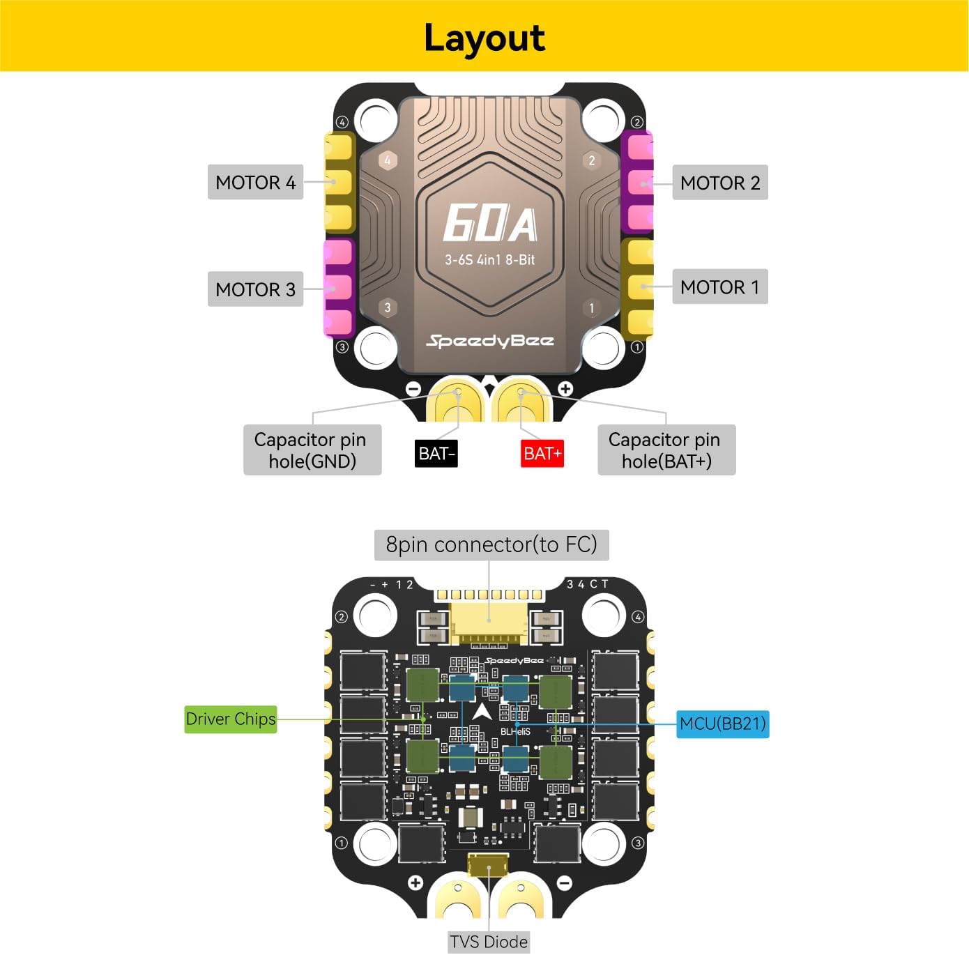
Image: Detailed layout of the SpeedyBee BLS 60A 4-in-1 ESC, showing motor pads, capacitor pin holes, 8pin connector to FC, driver chips, MCU (BB21), and TVS Diode.
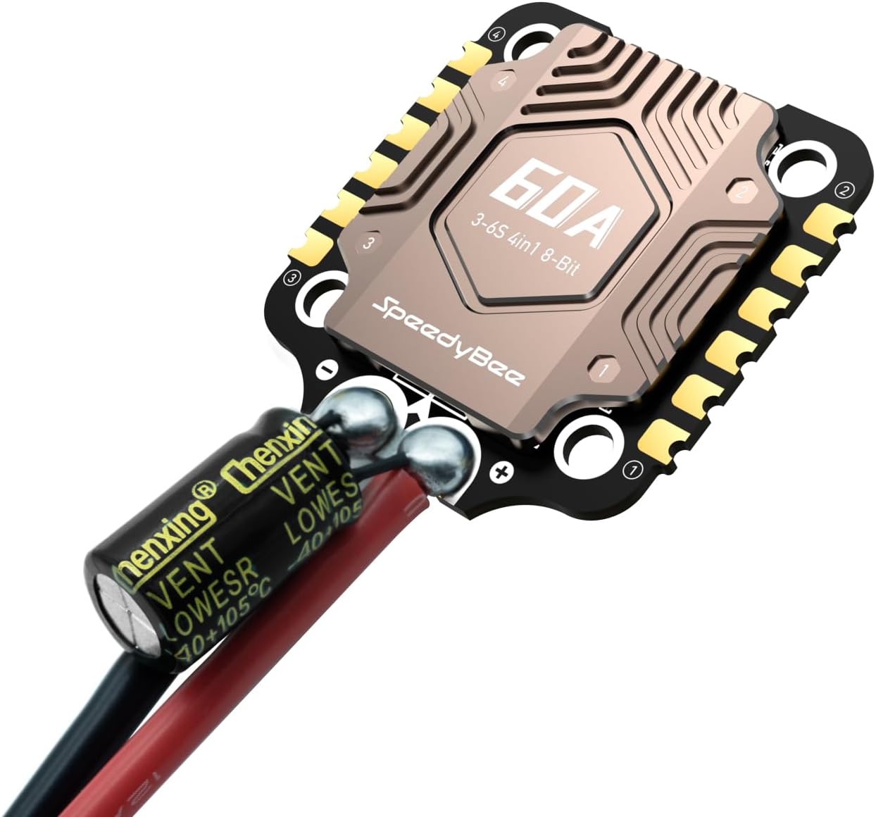
Image: SpeedyBee BLS 60A 4-in-1 ESC with the included 1000uF Low ESR Capacitor soldered, demonstrating proper connection for power filtering.

Image: Close-up view of the ESC filtering components, including TVS Diode Surge Protection, TDK 35V MLCC Filter & Energy Capacitor, and 35V 1000uF high-frequency low-ESR capacitor.
3.3. Physical Dimensions and Weight
- Package Dimensions: 4.72 x 2.36 x 1.26 inches
- Item Weight: 3.84 ounces (approx. 108.86 grams)
- Stack Weight: 34g (approx.)

Image: Technical drawing showing the precise dimensions of the SpeedyBee F405 V4 Flight Controller and the 60A 4-in-1 ESC, including mounting hole spacing and overall height when stacked, along with the total weight of 34g.
4. Wiring Diagram
The following diagrams illustrate the various connection possibilities for the SpeedyBee F405 V4 60A Flight Controller Stack with common FPV components.

Image: Comprehensive wiring diagram for the SpeedyBee F405 V4 Flight Controller, showing connections for Spektrum Receiver, ELRS Receiver, PPM Receiver, SBUS Receiver, Crossfire Nano Rx, LED Strip, Servo, Buzzer, GPS, Analog VTX, and DJI Air Unit.

Image: Diagram illustrating the connection of the SpeedyBee F405 V4 Flight Controller to the 60A 4-in-1 ESC, motors (Motor 1-4), XT60 Power Cable, and the recommended 1000uF Low ESR Capacitor. It also shows direct soldering options for FC and ESC.
Note 1: In order to prevent the stack from being burnt out by voltage spikes on powering up, it is strongly recommended to use the Low ESR capacitor included in the package.
Note 2: The FC and ESC can also be connected via direct soldering. Soldering pads definition is as follows.

Image: Diagrams showing specific cable connections for DJI O3 Air Unit (using 6-pin cable from O3 Air Unit), RunCam Link/Caddx Vista Air Unit (using 6-pin cable from F405 V4 stack), and DJI Air Unit V1 (using 6-pin cable from F405 V4 stack).
5. Setup and Installation
Follow these steps for proper installation and initial setup of your SpeedyBee F405 V4 60A Flight Controller Stack.
- Mounting: Securely mount the Flight Controller and ESC stack to your drone frame using the provided M3 screws and silicone grommets. Ensure proper orientation as per your drone's design and Betaflight configuration.
- Power Connection: Solder the XT60 power cable to the BAT+ and BAT- pads on the ESC. It is crucial to solder the included 35V 1000uF Low ESR Capacitor across the main battery pads (positive and negative) on the ESC to filter out voltage spikes and protect the electronics.
- Motor Connection: Solder your drone's motor wires to the corresponding motor pads (M1-M4) on the ESC. Pay attention to the motor order and direction as required by your flight controller firmware (e.g., Betaflight).
- FC-ESC Connection: Connect the Flight Controller to the ESC using the provided 8-pin cable. Ensure the cable is inserted correctly into the designated 8-pin connectors on both boards.
- Peripheral Connections: Connect other peripherals such as your receiver (Spektrum, ELRS, PPM, SBUS, Crossfire), FPV camera, VTX (Analog or DJI Air Unit), GPS module, and buzzer according to the wiring diagram in Section 4.
- SD Card Insertion: Insert a formatted MicroSD card (FAT32, C6 or C10 recommended) into the blackbox slot on the Flight Controller for flight data logging.

Image: Close-up of the Micro SD card slot on the Flight Controller, indicating compatibility with C10 and C6 cards and the requirement for FAT32 format.
5.1. Important Connection Notes
- SBUS Receiver with DJI Air Unit: If using an external SBUS receiver, do NOT connect the SBUS wire from the DJI O3/Vista/Link/Air Unit V1 to the flight controller. This can interfere with proper SBUS receiver operation.
- ELRS Receiver with DJI Air Unit: For some ELRS receivers, it is necessary to disconnect a specific wire from the DJI O3/Vista/Link/Air Unit V1 to ensure proper function. Refer to the ELRS receiver's manual for specific instructions.

Image: Diagram illustrating the warning against connecting the SBUS wire from the DJI O3/Vista/Link/Air Unit V1 when an external SBUS receiver is in use.

Image: Diagram illustrating the warning for ELRS receivers, indicating that a wire from the DJI O3/Vista/Link/Air Unit V1 may need to be disconnected for proper operation.
6. Operating Instructions
The SpeedyBee F405 V4 stack offers convenient wireless configuration and monitoring.
6.1. Wireless Betaflight Configuration
Utilize the SpeedyBee app on your smartphone to configure your Flight Controller and ESC wirelessly via Bluetooth. This allows for tuning and adjustments without needing a PC connection.
- Download App: Download the SpeedyBee app from your mobile device's app store.
- Connect: Power on your drone. Open the SpeedyBee app and connect to the Flight Controller via Bluetooth.
- Configure: Access various settings including PID tuning, motor directions, OSD settings, and more directly from your phone.

Image: Screenshot of the SpeedyBee mobile application interface, demonstrating wireless Betaflight configuration and PID tuning capabilities.
6.2. Changing Motor Directions Wirelessly
The SpeedyBee app allows for wireless motor direction changes, simplifying post-build or post-crash adjustments. This feature works for all BLHeli32 / BLHeli_S / BlueJay ESCs.

Image: A smartphone screen displaying the SpeedyBee app's motor configuration interface, showing how to wirelessly change motor directions.
6.3. Onboard Battery Life Indicator
The Flight Controller features a 4-level LED battery indicator, providing real-time battery status without an external checker.
- 4 LEDs solid: 75%-100% battery
- 3 LEDs solid: 50%-75% battery
- 2 LEDs solid: 25%-50% battery
- 1 LED solid: 10%-25% battery
- 1 LED blinking: Less than 10% battery

Image: Close-up of the Flight Controller showing the 4-level LED battery indicator and its corresponding battery percentage ranges.
6.4. LED Pads with Simple Switching
The Flight Controller provides 4 sets of LED pads for connecting LED strips. You can cycle through different LED presets by pressing the BOOT button.

Image: Diagram showing the location of the four LED pads on the Flight Controller, designed for connecting external LED strips.
7. Maintenance
Proper maintenance ensures the longevity and optimal performance of your SpeedyBee F405 V4 60A Flight Controller Stack.
- Regular Inspection: Periodically inspect all solder joints for cracks or cold joints. Check for any loose wires or damaged components.
- Cleaning: Keep the boards clean from dust, dirt, and debris. Use a soft brush or compressed air. Avoid using liquids directly on the electronics.
- Firmware Updates: Regularly check for and apply the latest Betaflight firmware updates for the F405 Flight Controller and BLHeli_S firmware updates for the ESC. This can improve performance and fix bugs.
- Capacitor Check: Ensure the Low ESR capacitor remains securely soldered and shows no signs of damage or bulging.
- Storage: When not in use, store the stack in a dry, cool environment, away from direct sunlight and extreme temperatures.
8. Troubleshooting
This section addresses common issues you might encounter with your SpeedyBee F405 V4 60A Flight Controller Stack.
- No Power/No Lights:
- Check main battery connection and polarity.
- Verify all power cables are securely soldered and not short-circuited.
- Ensure the 8-pin cable connecting FC and ESC is properly seated.
- Motors Not Spinning/Incorrect Direction:
- Confirm motor wires are correctly soldered to the ESC pads.
- Use the SpeedyBee app to check and adjust motor directions wirelessly.
- Verify ESC calibration in Betaflight.
- Check for continuity on motor pads and motor windings.
- Bluetooth Connection Issues:
- Ensure the Flight Controller is powered on.
- Restart the SpeedyBee app and your phone's Bluetooth.
- Move closer to the drone to ensure good signal strength.
- Check Betaflight configuration for Bluetooth settings.
- Unstable Flight/Oscillations:
- Review PID tuning settings in Betaflight via the SpeedyBee app.
- Ensure the Flight Controller is securely mounted and isolated from vibrations using the silicone grommets.
- Check for bent or damaged propellers.
- Blackbox Not Recording:
- Ensure a MicroSD card is inserted and properly formatted to FAT32.
- Check Betaflight settings to ensure blackbox logging is enabled and configured correctly.
- Try a different MicroSD card.
- Interference with SBUS/ELRS Receiver:
- Refer to Section 5.1 for specific warnings regarding DJI Air Unit connections and external receivers. Disconnect conflicting wires as advised.
9. Warranty and Support
For warranty information and technical support, please refer to the official SpeedyBee website or contact their customer service directly. Keep your proof of purchase for any warranty claims.
Official Website: www.speedybee.com
Amazon Product Page: SpeedyBee F405 V4 60A Flight Controller Stack
Related Documents - F405 V4 60A Flight Controller Stack
 |
SpeedyBee F405 V3 60A Stack: Flight Controller and ESC Manual Comprehensive guide to the SpeedyBee F405 V3 Flight Controller and BLS 60A 4-in-1 ESC stack, covering specifications, installation, connections, firmware updates, and parameter tuning. |
 |
SpeedyBee F405 V4 BLS 60A 30x30 Stack User Manual User manual for the SpeedyBee F405 V4 BLS 60A 30x30 Stack, detailing specifications, connections, configuration, and firmware updates for drone flight controllers and ESCs. |
 |
SpeedyBee F405 V4 BLS 60A 30x30 Stack User Manual User manual for the SpeedyBee F405 V4 Flight Controller and BLS 60A 4-in-1 ESC Stack. Includes specifications, connection diagrams, setup instructions, and firmware update procedures. |
 |
SpeedyBee F405 V4 BLS 60A 30x30 Stack User Manual User manual for the SpeedyBee F405 V4 BLS 60A 30x30 Stack, covering flight controller and ESC specifications, installation, connections, and configuration. |
 |
SpeedyBee F405 V3 BLS 60A 30x30 Stack User Manual User manual for the SpeedyBee F405 V3 BLS 60A 30x30 Stack, covering overview, flight controller and ESC specifications, connections, and configuration. |
 |
SpeedyBee F405 V3 BLS 60A Stack: Flight Controller and ESC Manual Comprehensive guide to the SpeedyBee F405 V3 Flight Controller and BLS 60A 4-in-1 ESC stack. Learn about specifications, dimensions, package contents, connection methods, app and FC configuration, firmware updates, and ESC setup. |
Ask a question about this manual
Ask about setup, troubleshooting, compatibility, parts, safety, or missing instructions. Manuals+ will review the question and use this page’s manual context to help answer it.