
1. Introduction
Thank you for choosing the GEPRC GEP-DS20 Frame. This manual provides essential information for the proper assembly, integration, and maintenance of your new drone frame. Please read these instructions carefully before proceeding with any installation to ensure optimal performance and longevity of your product.
2. Product Overview
The GEPRC GEP-DS20 is a lightweight and modular frame designed for micro FPV drones, specifically suited for 2-inch propellers. Its integrated protective frame enhances durability and safety, making it an excellent choice for various flight applications.
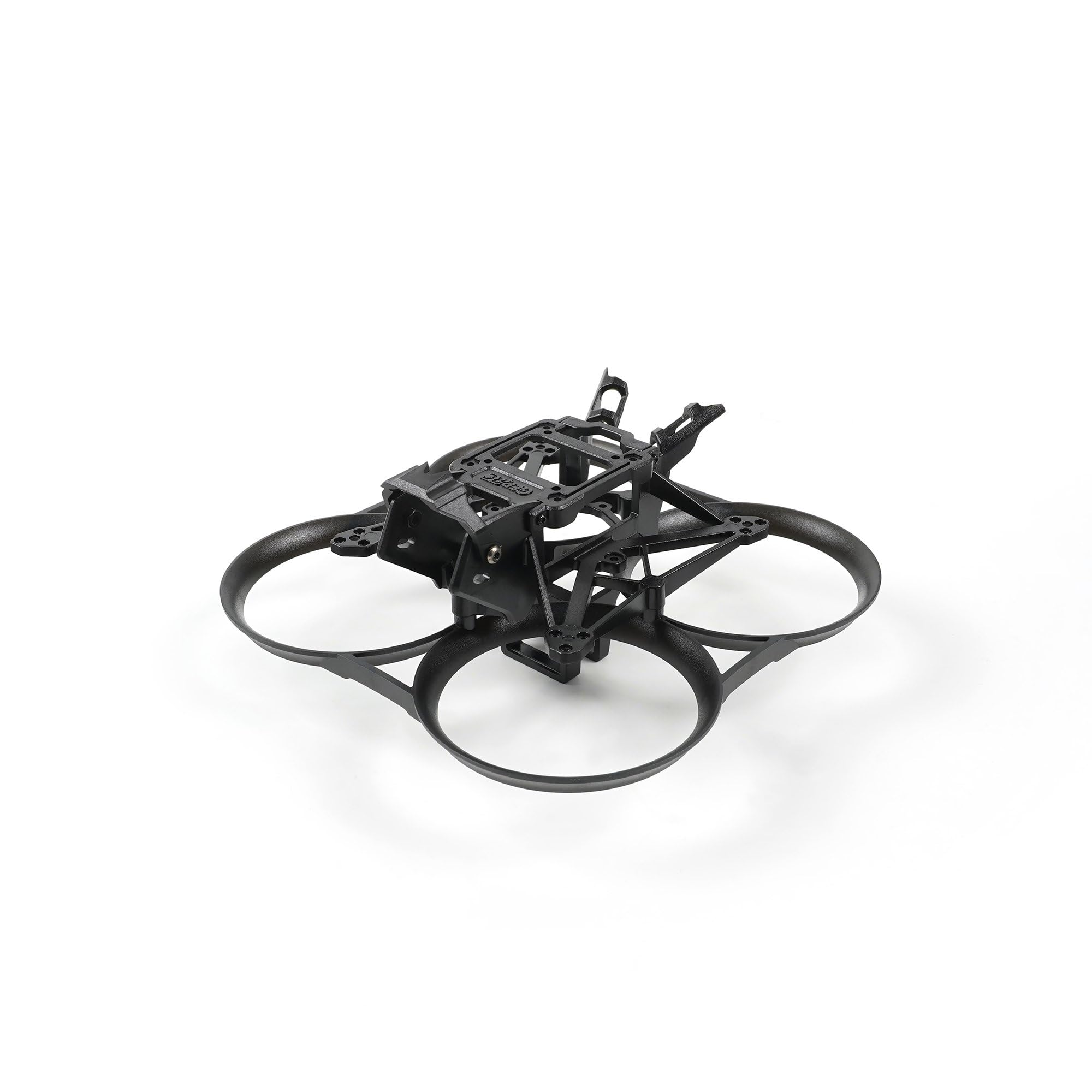
This image shows the GEPRC GEP-DS20 Frame from the front, highlighting its integrated protective ducts and central mounting area.
3. Package Contents
Please verify that all the following components are included in your package:
- 1 x Integrated Protective Frame
- 1 x Main Frame
- 1 x VTX Mounting Plate
- 1 x Camera Protective Cap
- 1 x Screw Pack (various screws for assembly)
- 2 x VTX Antenna
- 1 x 1.5mm L-type Screwdriver
- 1 x Torx Screwdriver
4. Assembly and Setup
Follow these general steps for assembling your GEP-DS20 Frame and integrating your electronic components. Specific component installation may vary based on your chosen parts.
4.1. Frame Assembly
- Attach the main frame to the integrated protective frame using the provided screws. Ensure all connections are secure.
- Install the VTX mounting plate onto the main frame.
- Secure the camera protective cap to the designated area.

A top-down view of the GEPRC GEP-DS20 Frame, illustrating the layout for flight controller and video transmitter mounting.
4.2. Component Installation
- Flight Controller (FC) / Electronic Speed Controller (ESC) Stack: Mount your FC/ESC stack using the 25.5mm x 25.5mm mounting pattern. Use appropriate standoffs and screws from your FC/ESC kit.
- Video Transmitter (VTX): The frame supports 20mm x 20mm or 25.5mm x 25.5mm VTX mounting. Secure your VTX to the VTX mounting plate. Connect the VTX antennas.
- Camera: The frame is designed for 19mm/20mm cameras. Carefully install your camera into the camera mounting bracket and secure it.
- Motors: Attach your motors to the motor mounting points using the 3-M1.4-6.6mm pattern. Ensure motor wires are routed safely and securely.
- Propellers: Once all electronics are installed and tested, attach the 2-inch propellers. Ensure they are oriented correctly for your flight controller's motor direction settings.

This image presents a side view of the GEPRC GEP-DS20 Frame, showing the camera mounting bracket and overall profile.

An angled view of the GEPRC GEP-DS20 Frame, detailing the motor mounting points and propeller guard structure.

A rear angled view of the GEPRC GEP-DS20 Frame, showing the battery strap slot and rear component access.
5. Operation Considerations
As the GEP-DS20 is a frame, its 'operation' is directly tied to the electronic components you install. Ensure all components are correctly wired, configured, and tested according to their respective manuals before flight. Always perform a pre-flight check to verify propeller direction, motor function, and control surface response.
6. Maintenance
Regular maintenance will extend the life of your GEP-DS20 Frame:
- Inspection: Periodically inspect the frame for cracks, stress marks, or loose screws, especially after any hard landings or crashes.
- Cleaning: Clean the frame with a soft, dry cloth. Avoid using harsh chemicals that could damage the plastic material.
- Component Check: Ensure all mounted components (FC, VTX, camera, motors) remain securely fastened.
- Replacement: If any part of the frame is significantly damaged, replace it immediately to prevent further issues during flight.
7. Troubleshooting
While the frame itself has few points of failure, issues often arise from improper assembly or component integration. Consider the following:
- Vibrations: Excessive vibrations can indicate loose motor screws, unbalanced propellers, or a damaged frame arm. Inspect and tighten/replace as necessary.
- Component Movement: If a component (e.g., camera, VTX) is loose, re-secure it with appropriate screws or mounting hardware.
- Cracked Frame: A cracked frame can lead to instability and component damage. Replace any cracked or broken frame parts immediately.
For issues related to electronic components, refer to their respective instruction manuals or manufacturer support.
8. Specifications
| Feature | Specification |
|---|---|
| Model | GEP-DS20 Frame |
| Frame Dimension | 126mm x 126mm x 57mm |
| Wheelbase | 90mm |
| FC Mount | 25.5mm x 25.5mm |
| VTX Mount | 20mm x 20mm / 25.5mm x 25.5mm |
| Motor Mount | 3-M1.4-6.6mm |
| Camera Size | 19mm / 20mm |
| Battery Slot Width | 17.3mm x 13.5mm |
| Propellers | 2 inch |
| Weight | 26g |
| Material | Plastic |
| Color | Black |
| Product Dimensions | 4.9 x 4.9 x 2.2 inches |
9. Warranty and Support
GEPRC products are manufactured to high-quality standards. For warranty information or technical support, please refer to the official GEPRC website or contact your authorized dealer. Keep your purchase receipt as proof of purchase.


