1. Introduction
This manual provides comprehensive instructions for the safe and effective operation of the ZOYI ZT303 Digital Multimeter. The ZT303 is a high-precision, auto-ranging measurement tool designed for professionals and enthusiasts, capable of measuring voltage, current, resistance, capacitance, frequency, and duty cycle. Please read this manual thoroughly before use to ensure proper operation and to prevent potential hazards.
2. Safety Information
To ensure safe operation and service of the meter, follow these instructions. Failure to observe these warnings can result in severe injury or death.
- Always ensure the meter is in the correct function and range before making measurements.
- Do not use the meter if it appears damaged or if the test leads are damaged.
- Do not apply more than the rated voltage, as marked on the meter, between the terminals or between any terminal and earth ground.
- Use extreme caution when working with voltages above 30V AC RMS, 42V peak, or 60V DC. These voltages pose a shock hazard.
- Disconnect the test leads from the circuit before changing functions.
- Remove the test leads from the meter before opening the battery cover.
- Do not operate the meter with the battery cover removed.
- Adhere to local and national safety codes.
3. Product Overview
The ZOYI ZT303 Digital Multimeter features a clear display, a rotary switch for function selection, and various input jacks for test leads.

Figure 3.1: Front view of the ZOYI ZT303 Digital Multimeter, showing the display, rotary switch, and input terminals.
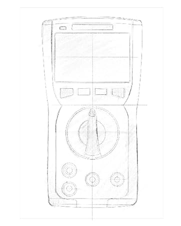
Figure 3.2: Technical drawing illustrating the internal layout or design elements of the ZOYI ZT303 Digital Multimeter.
3.1. Components
- LCD Display: Shows measurement readings, units, and function indicators.
- Function Buttons: For selecting specific modes (e.g., RANGE, REL, MAX/MIN, Hz, SELECT, HOLD).
- Rotary Switch: Used to select the desired measurement function (e.g., V~, V-, A~, A-, Ω, NCV).
- Input Jacks:
- COM Jack: Common terminal for all measurements. Connect the black test lead here.
- VHzΩCAP Diode Jack: Input for voltage, frequency, resistance, capacitance, and diode/continuity tests. Connect the red test lead here for these functions.
- mAµA Jack: Input for milliampere and microampere current measurements. Connect the red test lead here for these functions.
- 10A Jack: Input for 10 Ampere current measurements. Connect the red test lead here for high current measurements.
4. Setup
4.1. Battery Installation
- Ensure the multimeter is powered off and disconnect all test leads.
- Locate the battery compartment cover on the back of the unit.
- Unscrew the retaining screw(s) and remove the cover.
- Insert new batteries (e.g., 2 x AAA or 9V, refer to the battery compartment for specific type) observing the correct polarity.
- Replace the battery cover and secure it with the screw(s).
4.2. Connecting Test Leads
Always connect the black test lead to the COM jack. Connect the red test lead to the appropriate input jack based on the measurement function:
- For Voltage, Resistance, Capacitance, Frequency, Diode, and Continuity: Connect the red lead to the VHzΩCAP Diode jack.
- For mA/µA Current: Connect the red lead to the mAµA jack.
- For 10A Current: Connect the red lead to the 10A jack.
5. Operating Instructions
5.1. Power On/Off
Turn the rotary switch from the "OFF" position to any desired measurement function to power on the meter. To power off, turn the rotary switch back to the "OFF" position.
5.2. Auto Ranging
The ZT303 features auto-ranging, which automatically selects the appropriate measurement range. For manual range selection, press the RANGE button.
5.3. DC/AC Voltage Measurement (V)
- Set the rotary switch to the V~ (AC Voltage) or V- (DC Voltage) position.
- Connect the black test lead to the COM jack and the red test lead to the VHzΩCAP Diode jack.
- Connect the test probes across the circuit or component to be measured.
- Read the voltage value on the LCD display.
5.4. DC/AC Current Measurement (A, mA, µA)
Caution: Never connect the meter in parallel to a voltage source when measuring current. This can damage the meter and the circuit.
- Set the rotary switch to the appropriate current range (A~, A-, mAµA~, mAµA-).
- Connect the black test lead to the COM jack. Connect the red test lead to the mAµA jack for low current or the 10A jack for high current.
- Open the circuit where current is to be measured and connect the meter in series with the load.
- Read the current value on the LCD display.
5.5. Resistance Measurement (Ω)
Caution: Ensure the circuit is de-energized and all capacitors are discharged before measuring resistance.
- Set the rotary switch to the Ω position.
- Connect the black test lead to the COM jack and the red test lead to the VHzΩCAP Diode jack.
- Connect the test probes across the component to be measured.
- Read the resistance value on the LCD display.
5.6. Capacitance Measurement (F)
Caution: Ensure the capacitor is fully discharged before measurement to prevent damage to the meter.
- Set the rotary switch to the CAP position (often shared with Ω or Diode, use SELECT button if needed).
- Connect the black test lead to the COM jack and the red test lead to the VHzΩCAP Diode jack.
- Connect the test probes across the capacitor terminals.
- Read the capacitance value on the LCD display.
5.7. Frequency/Duty Cycle Measurement (Hz/%)
- Set the rotary switch to the Hz/% position (often shared with voltage or other functions, use SELECT button if needed).
- Connect the black test lead to the COM jack and the red test lead to the VHzΩCAP Diode jack.
- Connect the test probes across the signal source.
- Read the frequency or duty cycle value on the LCD display.
5.8. Diode Test and Continuity Test
- Set the rotary switch to the Diode/Continuity position. Use the SELECT button to toggle between diode test and continuity test.
- Connect the black test lead to the COM jack and the red test lead to the VHzΩCAP Diode jack.
- Diode Test: Connect the red probe to the anode and the black probe to the cathode of the diode. A forward voltage drop will be displayed. Reverse the probes; an "OL" (Overload) reading indicates a good diode.
- Continuity Test: Connect the probes across the circuit or component. A continuous beep and a low resistance reading indicate continuity.
5.9. Non-Contact Voltage (NCV) Detection
- Set the rotary switch to the NCV position.
- Move the top part of the meter close to the conductor or outlet.
- The meter will emit an audible beep and/or flash an LED indicator when AC voltage is detected.
5.10. Data Hold Function
Press the HOLD button to freeze the current reading on the display. Press it again to release the hold function.
5.11. MAX/MIN Function
Press the MAX/MIN button to enter MAX/MIN recording mode. The meter will display the maximum or minimum reading detected since the mode was activated. Press again to cycle between MAX, MIN, and current reading. Hold to exit.
5.12. Relative Measurement (REL)
Press the REL button to store the current reading as a reference value. Subsequent measurements will be displayed as the difference from this reference value. Press again to exit relative mode.
6. Maintenance
6.1. Cleaning
Wipe the case with a damp cloth and mild detergent. Do not use abrasives or solvents. Ensure the meter is completely dry before use.
6.2. Battery Replacement
When the low battery indicator appears on the display, replace the batteries as described in Section 4.1. Prompt replacement ensures accurate readings and proper operation.
6.3. Fuse Replacement
If the current measurement function fails, the fuse may need replacement. Refer to the specific fuse ratings printed near the input jacks or inside the battery compartment. Fuse replacement typically involves opening the back case (after removing batteries) and carefully replacing the blown fuse with one of the identical type and rating. If unsure, consult a qualified technician.
7. Troubleshooting
| Problem | Possible Cause | Solution |
|---|---|---|
| No display or dim display | Low or dead batteries | Replace batteries (Section 4.1) |
| "OL" (Overload) displayed | Measurement exceeds selected range or meter's maximum capacity | Select a higher range (if in manual range) or ensure measurement is within meter's limits. |
| Incorrect readings | Incorrect function selected, poor test lead connection, or damaged test leads | Verify function, check lead connections, inspect and replace damaged leads. |
| Current measurement not working | Blown fuse | Replace fuse (Section 6.3) |
8. Specifications
| Feature | Detail |
|---|---|
| Brand | ZOYI |
| Model Number | ZT303 |
| Product Dimensions | 4.53 x 1.97 x 7.68 inches |
| Item Weight | 14.11 ounces (399.98 Grams) |
| Power Source | Battery Powered |
| Color | Blue |
| Display | Digital LCD, 19999 Counts (typical for ZT303 series) |
| Ranging | Auto/Manual Ranging |
| Special Features | True RMS, NCV, Data Hold, Backlight, MAX/MIN, REL |
Note: Detailed electrical specifications (e.g., voltage/current ranges, accuracy) are typically printed on the device or included in a separate specification sheet.
9. Warranty and Support
Warranty information for the ZOYI ZT303 Digital Multimeter is typically provided at the point of purchase or within the product packaging. For specific warranty terms, technical support, or service inquiries, please refer to the official ZOYI website or contact your authorized dealer.
For further assistance, visit: ZOYI Official Flagship Store on Amazon


