
MATRIX MPM-1010B
MATRIX MPM-1010B High Precision Power Meter User Manual
Comprehensive guide for setup, operation, and maintenance of your MPM-1010B Digital Power Meter.
1. Introduction
The MATRIX MPM-1010B is a high-precision digital power meter designed for accurate measurement of electrical parameters. It integrates voltage, current, power, and power factor testing into a single multi-functional instrument. Utilizing a high-speed processor and precision resistance direct sampling, the MPM-1010B ensures undistorted data and high accuracy, especially for various waveform measurements including half-wave, distorted wave, and symmetrical/unsymmetrical square waves.
This instrument is widely used in various industries such as mobile phone charger manufacturing, adapter production, switch power supply testing, household appliance quality control, and transformer analysis.

Figure 1: Front view of the MATRIX MPM-1010B High Precision Power Meter.
Key Features:
- 4-Window Display: Simultaneously displays Voltage (V), Current (A), Power (P), and Peak Current/Power Factor/Frequency (Apk/PF/F).
- Wide Measurement Range: Input voltage from 1V-300V, input current from 0.2mA-10A, and power range from 0.01W-3000W.
- High Precision: Achieves 0.4%RD+0.1%FS+ld accuracy.
- Wide Frequency Response: AC: 15Hz-650Hz, suitable for various waveforms.
- Alarm Function: Configurable upper and lower limits for current (A) and power (P) with sound and light alarms.
- RS-232 Communication: Standard interface for data logging and system integration.
- Direct Plug Mode: Improves safety and convenience by eliminating traditional terminal posts.

Figure 2: Key features of the MPM-1010B, including electrical parameter test, harmonic test, alarm function, RS-232, AC/DC dual purpose, and limit setting.
2. Safety Information
Please read and understand all safety instructions before operating the MATRIX MPM-1010B power meter. Failure to follow these instructions may result in electric shock, fire, or damage to the instrument.
- Always connect the instrument to a properly grounded power outlet.
- Do not operate the meter in wet or damp conditions.
- Ensure the power supply voltage switch (110V/220V) on the rear panel matches your local power supply before connecting the power cord.
- Do not exceed the maximum input voltage of 300V or maximum current of 10A.
- Disconnect power to the device under test before making or changing connections.
- Refer all servicing to qualified personnel. There are no user-serviceable parts inside.
- Keep the instrument away from strong electromagnetic fields.
3. Product Overview and Components
Front Panel:

Figure 3: Front panel layout of the MPM-1010B.
- Display: Four digital displays showing Voltage, Current, Power, and Apk/PF/F.
- Lock/Unlock Button: Toggles the lock status for current, power, and power factor display.
- Function Setting Buttons (Up/Down Arrows): Used to navigate menus and adjust settings.
- Volume Output Switch: Controls the audible alarm.
- SETUP Button: Enters the setting status for configuration.
- POWER Button: Toggles the instrument's power on/off.
- OK Button: Confirms selections or settings.
- High/Low Indicators: LEDs indicating if measured values are above or below set limits.
Rear Panel:

Figure 4: Rear panel connections of the MPM-1010B.
- AC SOURCE Input: Power input for the device under test.
- LOAD Output: Connection point for the load being tested.
- RS-232 Port: Serial communication port for connecting to a computer.
- Power Input: AC power input for the MPM-1010B itself.
- Power Supply Voltage Switching: Switch to select between 110V and 220V operation.
4. Setup and Connection
Follow these steps to set up your MATRIX MPM-1010B power meter:
- Power Supply Voltage Selection: Locate the power supply voltage switch on the rear panel (Figure 4, item 5). Ensure it is set to match your local power supply (110V or 220V).
- Connect Power: Connect the provided power cord to the "Power Input" port on the rear panel (Figure 4, item 4) and plug the other end into a grounded AC outlet.
- Connect Device Under Test (DUT):
- Connect the AC power source for your DUT to the "AC SOURCE Input" port on the rear panel (Figure 4, item 1).
- Connect the DUT itself to the "LOAD Output" port on the rear panel (Figure 4, item 2).
- RS-232 Connection (Optional): If you wish to connect the meter to a computer for data logging or control, use an RS-232 serial cable to connect the "RS-232 Port" (Figure 4, item 3) on the rear panel to your computer's serial port or a USB-to-serial adapter.

Figure 5: The MPM-1010B features an RS-232 port for computer connectivity and data recording.
- Power On: Press the "POWER" button on the front panel (Figure 3, item 6) to turn on the instrument.
5. Operating Instructions
Basic Measurement:
Once powered on and connected to a load, the MPM-1010B will automatically display the measured values on its four-window display:
- Voltage (V): Top-left display.
- Current (A): Top-right display.
- Power (P): Bottom-left display.
- Apk / PF / F: Bottom-right display, cycling between Peak Current (Apk), Power Factor (PF), and Frequency (F).
Setting Upper and Lower Limits (Alarm Function):
The MPM-1010B allows you to set upper and lower limits for Current (A) and Power (P) to trigger sound and light alarms.
- Press the SETUP button (Figure 3, item 5) to enter the setting mode.
- Use the Up/Down Arrow buttons (Figure 3, item 3) to navigate through the parameters (e.g., A-High, A-Low, P-High, P-Low).
- Once the desired parameter is selected, press OK (Figure 3, item 7) to edit its value.
- Use the Up/Down Arrow buttons to adjust the numerical value.
- Press OK again to confirm the new value.
- Press SETUP to exit the setting mode.
When a measured value exceeds the set upper limit or falls below the set lower limit, the corresponding "High" or "Low" LED indicator (Figure 3, item 8) will illuminate, and an audible alarm will sound (if enabled).
Lock/Unlock Display:
Press the Lock/Unlock button (Figure 3, item 2) to freeze the current readings of Voltage, Current, Power, and Power Factor on the display. Press it again to unlock and resume real-time measurements.
Adjusting Volume:
Use the Volume Output Switch (Figure 3, item 4) to enable or disable the audible alarm sound.
RS-232 Communication:
For detailed data logging and analysis, connect the MPM-1010B to a computer via the RS-232 port. Refer to the separate RS-232 communication protocol document (if provided by MATRIX) for software requirements and command sets.
6. Specifications
The following table details the technical specifications of the MATRIX MPM-1010B High Precision Power Meter:
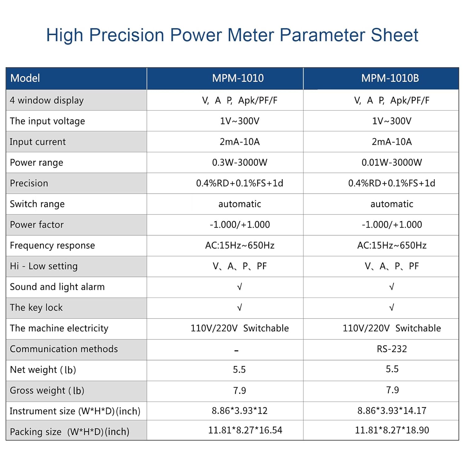
Figure 6: High Precision Power Meter Parameter Sheet comparing MPM-1010 and MPM-1010B.
| Parameter | Specification (MPM-1010B) |
|---|---|
| Display | 4 window display: V, A, P, Apk/PF/F |
| Input Voltage | 1V - 300V |
| Input Current | 0.2mA - 10A |
| Power Range | 0.01W - 3000W |
| Precision | 0.4%RD + 0.1%FS + ld |
| Switch Range | Automatic |
| Power Factor | -1.000 / +1.000 |
| Frequency Response | AC: 15Hz - 650Hz |
| Hi - Low Setting | A, P |
| Sound and Light Alarm | Yes |
| Key Lock | Yes |
| Machine Electricity | 110V/220V Switchable |
| Communication Methods | RS-232 |
| Net Weight | 5.5 lb (2.5 kg) |
| Instrument Size (W*H*D) | 8.86 x 3.93 x 14.17 inches (225 x 100 x 360 mm) |
7. Maintenance and Care
To ensure the longevity and accurate performance of your MPM-1010B, follow these maintenance guidelines:
- Cleaning: Use a soft, dry cloth to clean the exterior of the instrument. Do not use abrasive cleaners or solvents.
- Storage: Store the meter in a cool, dry place away from direct sunlight and extreme temperatures.
- Calibration: Regular calibration by qualified personnel is recommended to maintain measurement accuracy, especially in critical applications.
- Avoid Impact: Protect the instrument from physical shocks and vibrations.
8. Troubleshooting
This section provides solutions to common issues you might encounter with your MPM-1010B.
| Problem | Possible Cause | Solution |
|---|---|---|
| Instrument does not power on. | No power from outlet; Power cord not connected; Voltage switch incorrect. | Check power outlet; Ensure power cord is securely connected; Verify 110V/220V switch setting. |
| No readings on display. | Load not connected; DUT not powered; Measurement range exceeded. | Ensure DUT is properly connected to LOAD output; Verify DUT is powered on; Check if measured values are within the instrument's range. |
| Alarm sounds continuously. | Measured value outside set limits. | Check the measured values against the set upper/lower limits. Adjust limits or address the condition of the DUT. |
| RS-232 communication failure. | Incorrect cable; Driver issues; Software configuration. | Ensure correct RS-232 cable is used; Install necessary drivers; Verify software settings (baud rate, COM port). |
If the problem persists after attempting these solutions, please contact MATRIX customer support.
9. Warranty and Support
MATRIX TECHNOLOGY INC. provides a three-year warranty for the MPM-1010B High Precision Power Meter. This warranty covers defects in materials and workmanship under normal use.
For technical support, warranty claims, or service inquiries, please contact MATRIX customer service through the official MATRIX store on Amazon or visit the MATRIX website. Please have your product model number (MPM-1010B) and purchase details ready when contacting support.
Contact Information:
- Online Store: Visit the MATRIX Store on Amazon
- Manufacturer: MATRIX TECHNOLOGY INC.
Related documentsMPM-1010B


Ask a question about this manual
Ask about setup, troubleshooting, compatibility, parts, safety, or missing instructions. Manuals+ will review the question and use this page’s manual context to help answer it.