
1. Introduction
This instruction manual provides detailed guidance for the safe and effective use of the BACOENG R134a Car AC Recharge Kit. This kit is designed for adding R134a refrigerant to vehicle air conditioning systems, offering high efficiency and ease of use. Please read all instructions carefully before operation.

Image 1: The BACOENG R134a Car AC Recharge Kit, featuring a blue hose, an integrated pressure gauge, and various connection points.
2. Kit Components
The BACOENG R134a Car AC Recharge Kit includes the following components:
- Recharge Hose with Integrated Pressure Gauge: A 65 cm (25.6 inches) long hose equipped with a precise pressure gauge for monitoring system pressure.
- Low-Pressure Quick Coupler: Located at one end of the hose for secure connection to the vehicle's low-pressure AC port.
- R134a Can Tap (1/2" ACME Thread): Located at the other end of the hose, designed for single-puncture R134a refrigerant cans.
- Safety Valve: Integrated into the system to prevent accidental refrigerant leakage.

Image 2: Labeled diagram showing the pressure gauge, safety valve, low-pressure quick coupler, and can opener.

Image 3: Key dimensions of the recharge kit, showing the 65 cm hose length and segment measurements.
3. Setup Instructions
- Prepare the Refrigerant Can: Ensure you are using an R134a refrigerant can with a 1/2" ACME thread.
- Attach Can Tap: Screw the R134a can tap (the end with the valve handle) onto the refrigerant can until it is securely tightened. Do not pierce the can yet.
- Locate Vehicle's Low-Pressure Port: Identify the low-pressure service port on your vehicle's AC system. This port is typically smaller than the high-pressure port and often marked with an "L". Consult your vehicle's service manual if unsure.
- Connect Quick Coupler: Connect the low-pressure quick coupler (the blue end) to the vehicle's low-pressure service port. Push down firmly until it clicks into place, ensuring a secure connection.

Image 4: Illustration of connecting the R134a can tap to a refrigerant can.

Image 5: Detailed view of the blue low-pressure quick coupler.
4. Operating Instructions (Refrigerant Recharge)
Follow these steps to recharge your vehicle's AC system:
- Start Vehicle and AC: Start your vehicle and turn on the air conditioning to its maximum setting with the fan on high. Ensure the engine is running.
- Pierce Refrigerant Can: Turn the valve handle on the can tap clockwise until it pierces the refrigerant can. Then, turn it counter-clockwise to open the valve and allow refrigerant flow.
- Monitor Pressure: Observe the integrated pressure gauge. The gauge displays pressure in both psi and kg/cm². Refer to your vehicle's specifications for the recommended low-side pressure range. The gauge typically has colored zones:
- Green Zone: Indicates a low pressure level, suggesting refrigerant is needed.
- Yellow Zone (Full Alert): Indicates the system is approaching optimal charge.
- Red Zone (Danger): Indicates overpressure, which can damage the system.
- Add Refrigerant: Hold the refrigerant can upright. Gently shake the can while intermittently squeezing the trigger on the quick coupler for 5-10 seconds at a time. Release the trigger and check the pressure gauge. Repeat this process until the gauge reads within the recommended pressure range for your vehicle's AC system.
- Avoid Overcharging: Do not overcharge the system. Overcharging can lead to poor cooling performance and potential damage to AC components. If the gauge enters the red zone, stop immediately.
- Disconnect: Once the desired pressure is reached, close the valve on the can tap by turning it clockwise. Then, disconnect the low-pressure quick coupler from the vehicle's service port.

Image 6: Detailed view of the pressure gauge, showing colored zones for pressure monitoring.
5. Maintenance
- Cleaning: After each use, wipe down the hose and connectors with a clean, dry cloth to remove any refrigerant residue or dirt.
- Storage: Store the kit in a cool, dry place away from direct sunlight and extreme temperatures. Ensure all valves are closed before storage.
- Inspection: Periodically inspect the hose for cracks, leaks, or damage. Check the connectors for wear. Replace the kit if any significant damage is observed.
6. Troubleshooting
| Problem | Possible Cause | Solution |
|---|---|---|
| Refrigerant not flowing | Can tap not fully opened; can is empty; blockage in hose. | Ensure can tap valve is fully open. Replace can if empty. Check hose for kinks or blockages. |
| Gauge reads zero or very low after connecting | Low-pressure quick coupler not fully seated; AC system completely empty. | Ensure quick coupler is securely connected. If system is completely empty, a professional leak check and repair may be required before recharging. |
| Gauge reads in red zone (overpressure) | System is overcharged; high-pressure port connected instead of low-pressure. | Stop charging immediately. Consult a professional to safely relieve pressure. Always connect to the low-pressure port. |
| Refrigerant leakage during connection/disconnection | Loose connections; worn O-rings in quick coupler. | Ensure all connections are tight. Inspect O-rings and replace if damaged. The integrated safety valve minimizes leakage. |
7. Specifications
| Brand | BACOENG |
| Model Number | P1104FBAUK2 |
| Refrigerant Compatibility | R134a |
| Hose Length | 65 cm (25.6 inches) |
| Can Tap Thread | 1/2" ACME |
| Low-Pressure Coupler Size | 13mm (standard for R134a low-side) |
| Max Working Pressure (WP) | 600 psi |
| Max Burst Pressure (BP) | 3000 psi |
| Material | High-quality brass and rubber |
| Special Features | Integrated pressure gauge, safety valve, durable construction. |
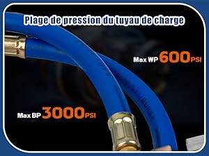
Image 7: Pressure ratings for the hose, indicating maximum working and burst pressures.
8. Warranty and Support
This BACOENG product comes with a Limited Warranty. For specific warranty terms and conditions, please refer to the product packaging or contact BACOENG customer support. For technical assistance or inquiries, please contact your retailer or the manufacturer directly.