
1. Product Overview
The Wishiot TCS3472 RGB Light Color Sensor Recognition Module is a color light-to-digital converter based on the AMS TCS3472XFN chip. It provides digital outputs for red, green, blue (RGB), and clear light sensing values. An integrated infrared blocking filter minimizes the infrared spectral component of incident light, ensuring accurate color measurements. This module features high sensitivity, a wide dynamic range, and includes IR blocking filters to reduce the effects of infrared and ultraviolet spectral components. It also offers ambient light intensity detection and a configurable interrupt function. Communication with the module is via the I2C interface. Dual-aperture versions are equipped with two LEDs to illuminate the object being sensed, enhancing measurement accuracy.
This module is designed for use with microcontrollers such as Arduino and STM32, with sample programs and datasheet files available upon request from customer service.
2. Specifications
| Parameter | Value |
|---|---|
| Operating Voltage | 3.3V / 5V |
| Control Chip | TCS3472XFN |
| Logic Voltage | 3.3V / 5V |
| Communication Interface | I2C |
| Brand | Wishiot |
| Model Name | WS-5107 |
| Included Components | Sensor Module |
| Compatible Devices | Raspberry Pi, Arduino, BeagleBone |
Product Dimensions

Image: Dimensions of the TCS3472 Color Sensor Module. The module measures approximately 31.3mm in length and 11.2mm in width, with the sensor area being 20.4mm.
3. Setup and Installation
Pinout Description
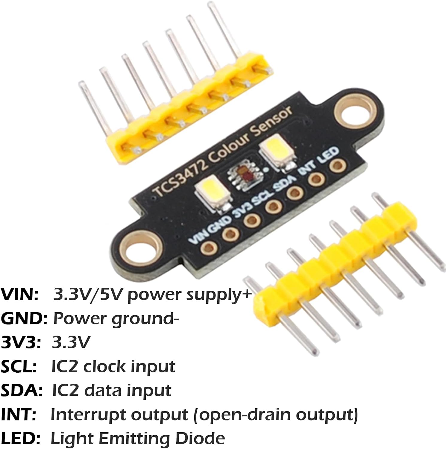
Image: Pinout diagram of the TCS3472 Color Sensor Module. The pins are labeled as follows: VIN (3.3V/5V power supply+), GND (Power ground-), 3V3 (3.3V), SCL (I2C clock input), SDA (I2C data input), INT (Interrupt output - open-drain output), and LED (Light Emitting Diode).
Wiring with Arduino
The TCS3472 module communicates via the I2C interface. When connecting to a 5V microcontroller like some Arduino boards, it is recommended to use a logic level converter as the sensor operates at 3.3V/5V logic levels. Ensure correct connections for VIN, GND, SCL, and SDA.

Image: Example wiring diagram for connecting the TCS3472 Color Sensor Module to an Arduino R3. VIN connects to 5V, GND to GND, SCL to A5, and SDA to A4 on the Arduino. This setup also includes a NeoPixel ring for visual feedback.
Software Setup
To use the module with Arduino or STM32, you will need to install the appropriate libraries. For Arduino, the Adafruit TCS3472 library is commonly used. Sample programs are available to help you get started with reading color and light intensity values.
4. Operating Instructions
The TCS3472 sensor can perform both ambient light intensity (lux) sensing and color sensing. The module provides linear RGB values by default, which can be further processed with gamma adjustment for human-perceptible color representation. The sensor's performance can be tuned using gain and integration time values.
Color Sensing with Integrated LEDs
For sensing the color of pigmented objects, the module's integrated LEDs should be used to illuminate the object. Place the object directly in front of the sensor, ensuring the LEDs provide sufficient light. The sensor will then output RGB values corresponding to the object's color.

Image: The sensor detecting the color of different objects (lime, apple, banana, and a smartphone). An external LED ring changes color to match the detected color, demonstrating the sensor's functionality.
Ambient Light Sensing
For measuring ambient light intensity (lux) or the color of an external light source, the module's integrated LEDs should be turned off. Point the sensor towards the light source or area where ambient light needs to be measured. The sensor will then provide light intensity and color data based on the external illumination.
Tuning Gain and Integration Time
Adjusting the gain and integration time settings is crucial for optimal performance. High gain or long integration times can lead to sensor saturation (overloading) in bright conditions, resulting in inaccurate readings. Conversely, low gain or short integration times might not capture enough light in dim environments. Experiment with these settings to find the best balance for your specific application and lighting conditions.
Operational Demonstration Video
Video: This video demonstrates the TCS3472 RGB Light Color Sensor in action, showing how it detects different colors and outputs corresponding RGB values. It highlights the use of the sensor with an Arduino setup and illustrates the effect of placing various colored objects in front of the sensor.
5. Maintenance
To ensure the longevity and accuracy of your TCS3472 RGB Light Color Sensor Module, follow these general maintenance guidelines:
- Keep Clean: Regularly clean the sensor's optical surface with a soft, dry, lint-free cloth to prevent dust or smudges from affecting readings. Avoid using abrasive materials or harsh chemicals.
- Handle with Care: The module contains sensitive electronic components. Avoid dropping it or subjecting it to excessive physical shock.
- Storage: Store the module in a dry, dust-free environment away from extreme temperatures and direct sunlight when not in use.
- Power Supply: Always ensure the power supply voltage is within the specified range (3.3V/5V) to prevent damage to the module.
6. Troubleshooting
If you encounter issues with your TCS3472 RGB Light Color Sensor Module, consider the following troubleshooting steps:
- No Readings/Incorrect Readings:
- Verify all wiring connections (VIN, GND, SCL, SDA) are secure and correct according to the pinout diagram.
- Ensure the power supply voltage is stable and within the 3.3V/5V range.
- Check if the I2C address is correctly configured in your software. The default I2C address for TCS3472 is 0x29.
- If using a 5V microcontroller, confirm that a logic level converter is properly installed and functioning.
- Clean the sensor's optical surface.
- Adjust the gain and integration time settings in your code. High gain in bright light can cause saturation, while low gain in dim light may result in insufficient data.
- LEDs Not Illuminating:
- Check the power supply to the module.
- Ensure the LED control pin (if applicable and used) is correctly configured and receiving the appropriate signal from your microcontroller.
- Software/Library Issues:
- Confirm that the correct library for the TCS3472 is installed and up to date in your development environment (e.g., Arduino IDE).
- Review sample code and ensure your implementation matches the library's requirements.
7. Warranty and Support
Warranty: There is no specific warranty description provided for this product.
Support: For technical assistance, sample programs, or datasheet files, please contact Wishiot customer service. They can provide the necessary resources to help you with your projects.