
1. Introduction
This manual provides essential information for the setup, operation, and maintenance of the Stemedu Heltec ESP32 915MHz LoRa V3 Development Board. This board is a versatile IoT development platform integrating Wi-Fi, Bluetooth Low Energy (BLE), and LoRa communication capabilities, featuring an onboard 0.96-inch 128x64 OLED display. It is designed for various intelligent scene applications, including Meshtastic and Arduino projects.

Figure 1: Heltec ESP32 915MHz LoRa V3 Development Boards with included accessories.
2. Package Contents
Verify that all items listed below are present in your package. If any components are missing or damaged, please contact customer support.
- 2 x Heltec ESP32 LoRa V3 SX1262 0.96 inch OLED Display Development Boards
- 2 x 868MHz/915MHz GSM IPX IPEX 1.13 UF.L Antennas
- 2 x Terminal Connector Cables
- 4 x Pin Headers
3. Product Overview and Key Differences (V2 vs. V3)
The Heltec WiFi LoRa 32 V3 board is an evolution of the V2, incorporating several key upgrades for enhanced performance and usability.

Figure 2: Comparison of key specifications between WiFi LoRa 32 V2 and V3.
Key Differences:
- Microcontroller Unit (MCU): V3 utilizes the ESP32-S3FN8 dual-core processor, an upgrade from the V2's ESP32-D0WDQ6. This change affects GPIO pin definitions.
- LoRa Chip: V3 features the SX1262 LoRa chip, offering improved performance over the V2's SX1276/8.
- USB Interface: V3 incorporates a modern USB Type-C interface, replacing the Micro USB found on V2.
- Crystal Oscillator: V3 uses a high-precision temperature-compensated crystal oscillator for better stability.
- Low Power Features: V3 offers significantly lower power consumption in deep sleep mode (less than 10uA) compared to V2 (approximately 800uA).
- RF Circuitry: V3 includes better impedance matching for its RF circuits.
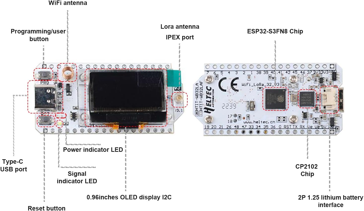
Figure 3: Top view comparison (V2 vs V3).

Figure 4: USB interface comparison (V2 vs V3).
4. Board Layout and Pinout
4.1. Component Identification
Familiarize yourself with the main components of the Heltec ESP32 LoRa V3 board as illustrated below.

Figure 5: Heltec ESP32 LoRa V3 Board Component Layout.
- WiFi Antenna: For 2.4GHz Wi-Fi communication.
- Programming/User Button (PRG): Used for entering bootloader mode or as a general-purpose button.
- Reset Button (RST): Resets the ESP32-S3 microcontroller.
- Type-C USB Port: For power supply, data communication, and programming.
- Power Indicator LED: Illuminates when the board is powered.
- Signal Indicator LED: User-programmable LED.
- 0.96-inch OLED Display I2C: 128x64 pixel monochrome display.
- LoRa Antenna IPEX Port: Connects to the external LoRa antenna.
- ESP32-S3FN8 Chip: Dual-core microcontroller with Wi-Fi and BLE.
- CP2102 Chip: USB-to-UART bridge for serial communication.
- 2P 1.25 Lithium Battery Interface: For connecting a 3.7V LiPo battery (battery not included).
4.2. Pinout Diagram
The pinout diagram details the functionality of each pin on the Heltec ESP32 LoRa V3 board. Refer to this diagram for proper connection and programming.

Figure 6: Heltec ESP32 LoRa V3 Pinout Diagram.
Legend: Physical Pin (Grey), GND (Black), Power (Red), GPIO (Pink), ADC/DAC (Green), Serial SPI I2C (Light Blue), Connected (Dark Blue), Other (White), Pull Up/Down (Yellow Arrows).
5. Setup and Initial Use
5.1. Antenna Connection
Before powering on the board, ensure the 915MHz LoRa antenna is securely connected to the IPEX port. Operating the LoRa module without an antenna can cause damage.
- Carefully align the IPEX connector on the antenna cable with the IPEX port on the board.
- Gently press down until you feel a click, indicating a secure connection.
5.2. Power Supply
The board can be powered via the USB Type-C port or a 3.7V lithium battery.
- USB Type-C: Connect a standard USB Type-C cable to the board and a power source (e.g., computer USB port, USB wall adapter). The Power Indicator LED will illuminate.
- Lithium Battery: Connect a 3.7V lithium battery to the 2P 1.25mm connector. The board includes a charging circuit for connected batteries when powered via USB.
5.3. Development Environment Setup
To program the Heltec ESP32 LoRa V3 board, you will typically use the Arduino IDE or PlatformIO.
- Install the Arduino IDE or PlatformIO.
- Add the ESP32 board support package for your chosen IDE. Specific instructions can be found on the official Heltec Automation website or Espressif documentation.
- Install necessary libraries for LoRa, OLED display, and other functionalities (e.g., Heltec ESP32 library).
- Connect the board to your computer via the USB Type-C cable.
- Select the correct board model and COM port in your IDE.
6. Operating Instructions
6.1. Basic LoRa Communication
The LoRa module allows for long-range, low-power wireless communication.
- Transmitting: Program one board to send data packets using the LoRa library. Ensure the correct frequency (915MHz for this model) and spreading factor are configured.
- Receiving: Program a second board to listen for incoming LoRa packets on the same frequency and with matching parameters.
- Example: For Meshtastic applications, refer to the official Meshtastic documentation for firmware installation and configuration.
6.2. Wi-Fi and BLE Functionality
The ESP32-S3 microcontroller supports standard Wi-Fi (802.11 b/g/n) and Bluetooth Low Energy (BLE) protocols.
- Wi-Fi: Use standard ESP-IDF or Arduino Wi-Fi libraries to connect to access points, host soft APs, or establish peer-to-peer connections.
- BLE: Implement BLE client or server roles for short-range communication with other BLE-enabled devices.
6.3. OLED Display Usage
The onboard 0.96-inch OLED display can be used to show sensor data, status messages, or other information.
- Utilize an appropriate OLED library (e.g., U8g2, Adafruit SSD1306) to initialize and draw graphics/text on the display.
- The display communicates via I2C. Ensure correct I2C pins are configured in your code.
7. Maintenance
To ensure the longevity and optimal performance of your Heltec ESP32 LoRa V3 board, follow these maintenance guidelines:
- Storage: Store the boards in an anti-static bag in a dry, cool environment when not in use.
- Cleaning: Use a soft, dry brush or compressed air to remove dust from the board. Avoid using liquids or harsh chemicals.
- Handling: Always handle the board by its edges to avoid touching sensitive components or introducing static discharge.
- Antenna Care: Ensure the LoRa antenna is not bent or damaged. Disconnect it carefully when transporting the board.
8. Troubleshooting
This section addresses common issues you might encounter.
- Board not recognized by computer:
- Ensure the USB Type-C cable is fully inserted and functional.
- Install the correct CP210x USB to UART Bridge drivers for your operating system.
- Try a different USB port or cable.
- Failed to upload code:
- Verify that the correct board and COM port are selected in your IDE.
- Press and hold the "PRG" (Boot) button, then press and release the "RST" (Reset) button, then release "PRG" to enter bootloader mode before uploading.
- Check for correct ESP32 board support package installation.
- OLED display not working:
- Ensure the OLED library is correctly installed and initialized in your code.
- Verify that the I2C pins used in your code match the board's pinout.
- Check for any physical damage to the display.
- LoRa communication issues:
- Confirm the LoRa antenna is securely connected.
- Ensure both transmitting and receiving boards are configured with matching frequencies, spreading factors, and other LoRa parameters.
- Check the range and environmental factors (obstacles, interference).
9. Technical Specifications
Detailed technical specifications for the Heltec ESP32 915MHz LoRa V3 board.
| Feature | Specification |
|---|---|
| Microcontroller | ESP32-S3FN8 Dual-core Processor |
| LoRa Chip | SX1262 |
| LoRa Frequency | 915MHz (863~928MHz supported) |
| Wi-Fi Standard | 802.11 b/g/n, up to 150Mbps |
| Bluetooth | Bluetooth Low Energy (BLE) |
| Display | 0.96-inch 128x64 OLED (I2C) |
| USB Interface | USB Type-C |
| Power Supply | USB Type-C (5V) or 3.7V Lithium Battery |
| Operating System | FreeRTOS (compatible with Arduino IDE, PlatformIO) |
| RAM | 512 KB SRAM |
| Flash Memory | 8 MB |
| Item Weight | 1.12 ounces (approx. 31.75 grams) |
| Dimensions | Refer to Figure 7 for detailed dimensions. |

Figure 7: Heltec ESP32 LoRa V3 Board Dimensions.
10. Warranty and Support
Stemedu products are designed for reliability and performance. For warranty information, technical support, or assistance with your Heltec ESP32 915MHz LoRa V3 board, please refer to the official Stemedu website or contact their customer service directly.
For additional resources, community forums, and example code, consider visiting the Heltec Automation official website or relevant online communities for ESP32 and LoRa development.
