
Generac RXSW200A3 & 7101
Generac 200 Amp Automatic Smart Transfer Switch Kit & Battery Heater Pad User Manual
Model: RXSW200A3 & 7101
1. Introduction and Product Overview
This manual provides essential information for the safe and efficient operation of your Generac 200 Amp Single Phase Automatic Smart Transfer Switch Kit and the Generac 7101 Battery Heater Pad. This combined system is designed to ensure continuous power supply during utility outages and maintain optimal battery performance for your standby generator.
The Generac Automatic Transfer Switch is engineered for use with single-phase generators equipped with an Evolution or Nexus Controller. It monitors utility power and automatically transfers the electrical load between utility and generator power, ensuring seamless operation. Its Digital Power Management (DPM) technology allows for the management of up to four individual HVAC (24 VAC controlled) loads without additional hardware.
The Generac 7101 Battery Heater Pad is designed to maintain the optimal temperature of your generator's battery, especially in colder climates. It activates automatically to prevent performance degradation due to low temperatures.
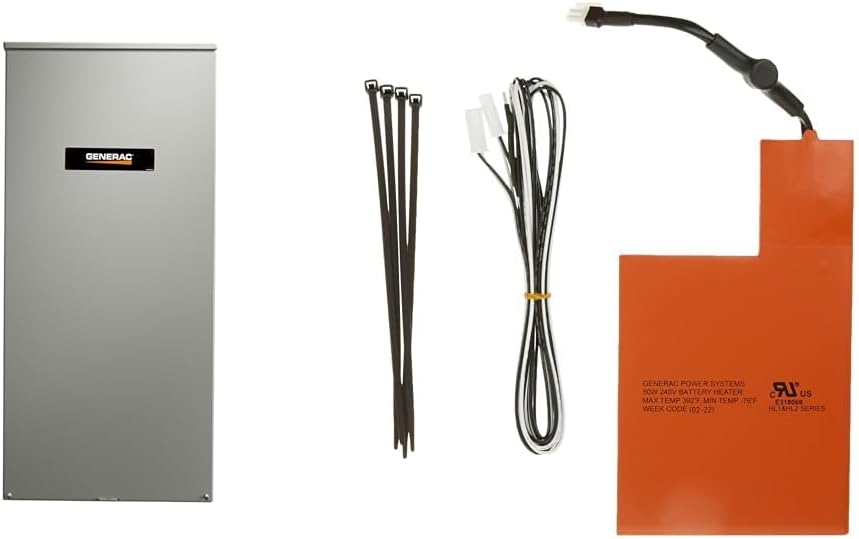
Figure 1: Overview of the Generac 200 Amp Automatic Smart Transfer Switch Kit and 7101 Battery Heater Pad, showing the transfer switch enclosure, battery heater pad, and associated wiring/ties.
2. Safety Information
WARNING: Installation and service must be performed by a qualified electrician or service technician. Improper installation or maintenance can result in serious injury, death, or property damage.
- Always disconnect all power sources before servicing the transfer switch or battery heater pad.
- Ensure all local electrical codes and regulations are followed during installation.
- Wear appropriate personal protective equipment (PPE), including safety glasses and insulated gloves.
- Do not operate the transfer switch or heater pad if any components are damaged.
- Keep children and unauthorized personnel away from the equipment.
3. Product Components
The Generac 200 Amp Automatic Smart Transfer Switch Kit and 7101 Battery Heater Pad include the following main components:
- Generac 200 Amp Automatic Smart Transfer Switch: Housed in an aluminum NEMA/UL type 3R enclosure.
- Generac 7101 Battery Heater Pad: Designed for 9kW-22kW air-cooled standby generators.
- Associated wiring and installation accessories (e.g., cable ties).
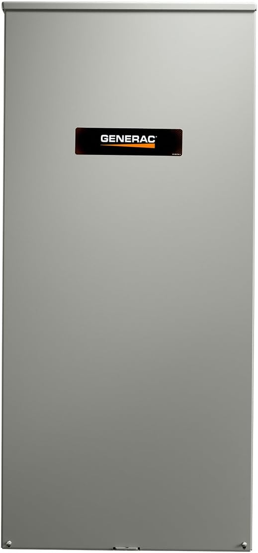
Figure 2: Exterior view of the Generac 200 Amp Automatic Smart Transfer Switch enclosure.

Figure 3: Interior view of the Generac 200 Amp Automatic Smart Transfer Switch, showing internal components and wiring terminals.

Figure 4: The Generac 7101 Battery Heater Pad, including its power cable and connection points.
4. Setup and Installation
Proper installation is crucial for the safe and effective operation of your transfer switch and battery heater pad. It is highly recommended that installation be performed by a certified electrician or Generac authorized service dealer.
4.1. Automatic Transfer Switch Installation
- Site Selection: Choose a location for the transfer switch that is accessible, protected from severe weather, and in close proximity to both the utility meter and the generator. The NEMA 3R enclosure is suitable for outdoor use.
- Mounting: Securely mount the transfer switch enclosure to a sturdy surface using appropriate hardware. Ensure it is level and plumb.
- Wiring Connections:
- Utility Power: Connect the utility power lines to the designated terminals within the transfer switch. This unit includes a service disconnect.
- Generator Power: Connect the generator power lines to the appropriate terminals.
- Load Connections: Connect the household electrical load to the transfer switch output terminals.
- Control Wiring: Connect the low-voltage control wires between the transfer switch and the generator's Evolution or Nexus Controller. Refer to your generator's manual for specific control wiring diagrams.
- Grounding and Bonding: Ensure proper grounding and neutral bonding as per local electrical codes.
- Final Checks: Before restoring power, double-check all connections for tightness and correct polarity.
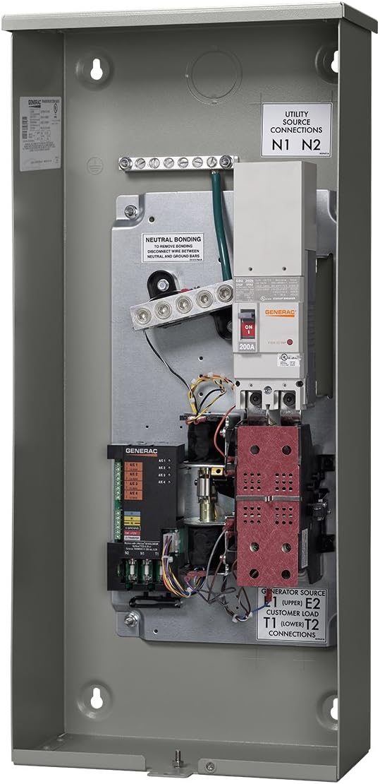
Figure 5: Angled interior view of the transfer switch, highlighting the utility source connections (N1, N2), generator source, and customer load connections.
4.2. Battery Heater Pad Installation
The Generac 7101 Battery Heater Pad is designed for easy installation under the generator battery. It is compatible with air-cooled standby generators manufactured in 2008 or later. Note: This heater pad is not required for use with AGM-style batteries.
- Battery Removal: Carefully disconnect and remove the generator battery from its tray.
- Pad Placement: Place the Generac 7101 Battery Heater Pad directly onto the battery tray, ensuring it is centered and flat.
- Battery Reinstallation: Carefully place the battery back onto the heater pad in the tray. Reconnect the battery terminals, ensuring correct polarity.
- Wiring Connection: Connect the heater pad's wiring to the designated low-voltage power source on your generator, as specified in your generator's installation manual.
- Secure Wiring: Use the provided cable ties to secure the heater pad wiring, preventing it from interfering with moving parts or being damaged.
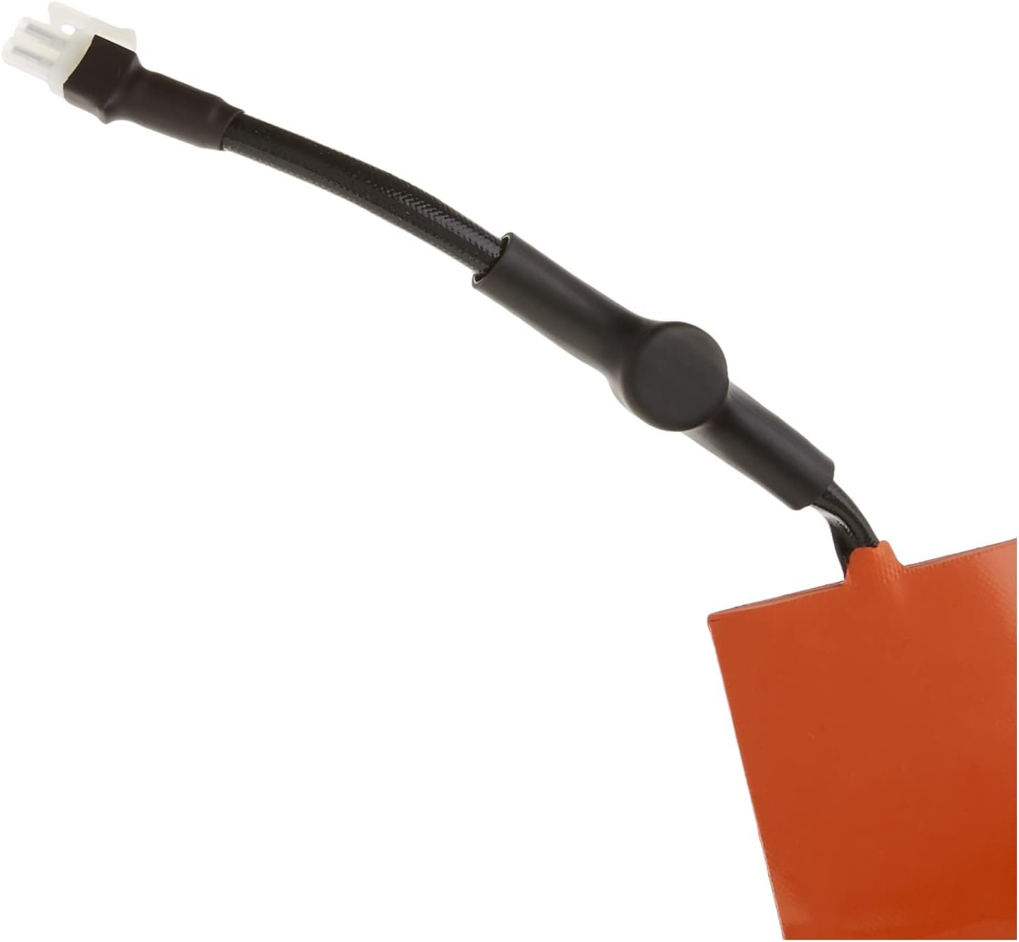
Figure 6: Close-up view of the connector for the Generac 7101 Battery Heater Pad.

Figure 7: Detailed view of the wiring for the Generac 7101 Battery Heater Pad.
5. Operating Instructions
5.1. Automatic Transfer Switch Operation
The Generac Automatic Transfer Switch operates autonomously to manage your home's power supply.
- Utility Power Monitoring: The transfer switch continuously monitors the incoming utility power for interruptions or significant voltage fluctuations.
- Automatic Transfer to Generator: Upon detecting a utility power outage, the transfer switch signals the standby generator to start. Once the generator reaches proper operating voltage and frequency, the transfer switch automatically disconnects the home from utility power and connects it to the generator power. This process is seamless and typically occurs within seconds.
- Digital Power Management (DPM): The integrated DPM allows the transfer switch to manage up to four 24 VAC controlled HVAC loads. During generator operation, if the total load approaches the generator's capacity, the DPM will shed non-essential HVAC loads to prevent overload, then reconnect them as capacity becomes available.
- Return to Utility Power: When stable utility power is restored, the transfer switch monitors it for a pre-set period to ensure stability. Once confirmed, it automatically transfers the electrical load back to utility power and signals the generator to cool down and shut off.
5.2. Battery Heater Pad Operation
The Generac 7101 Battery Heater Pad operates automatically based on ambient temperature to ensure your generator's battery remains at an optimal temperature for starting.
- Automatic Activation: The heater pad is equipped with a thermostat that activates the heating element when the ambient temperature drops to approximately 40°F (4.4°C).
- Automatic Deactivation: The heater pad will turn off when the battery temperature reaches approximately 55°F (12.8°C), preventing overheating and conserving energy.
- Continuous Monitoring: The heater pad continuously monitors the temperature, cycling on and off as needed to maintain the battery within the optimal temperature range.
6. Maintenance
Regular maintenance ensures the longevity and reliable operation of your Generac transfer switch and battery heater pad. It is recommended to have these components inspected annually by a qualified technician as part of your generator's maintenance schedule.
- Visual Inspection: Periodically inspect the transfer switch enclosure for any signs of damage, corrosion, or loose connections. Ensure the enclosure is sealed and free from debris.
- Wiring Check: Verify that all wiring connections are secure and free from fraying or damage.
- Cleanliness: Keep the exterior of the transfer switch and the area around the battery heater pad clean and free of obstructions.
- Battery Health: Regularly check your generator's battery health. While the heater pad helps with temperature, the battery itself still requires proper charging and occasional testing.
- Professional Service: For internal components of the transfer switch or any electrical issues, contact a Generac authorized service dealer. Do not attempt to service internal electrical components yourself.
7. Troubleshooting
This section provides basic troubleshooting steps for common issues. For complex problems, always contact a qualified Generac service technician.
| Problem | Possible Cause | Solution |
|---|---|---|
| Transfer switch does not transfer to generator during outage. |
|
|
| Transfer switch does not return to utility power. |
|
|
| Battery heater pad not warming battery. |
|
|
Important: Do not attempt electrical repairs if you are not qualified. Always prioritize safety.
8. Specifications
| Feature | Specification |
|---|---|
| Operation Mode | Automatic |
| Current Rating | 200 Amps |
| Operating Voltage | 240 Volts |
| Contact Type | Normally Open |
| Connector Type | 2 Pin |
| Terminal | Screw |
| Circuit Type | 1-way |
| Actuator Type | Hinge Lever |
| Contact Material | Steel |
| International Protection Rating | IP67 |
| Number of Positions | 1 |
| Specification Met | UL |
| Lower Temperature Rating (Heater Pad Activation) | 40 Degrees Fahrenheit (4.4°C) |
| Upper Temperature Rating (Heater Pad Deactivation) | 55 Degrees Fahrenheit (12.8°C) |
| Control Method | Touch (for DPM interface, if applicable) |
| Connectivity Protocol | X-10 (for DPM, if applicable) |
| Color | Orange (Heater Pad) |
| Wattage | 6000 Watts (General product specification) |
| Unit Count | 1.0 Count |
| Number of Items | 1 |
| Manufacturer | Generac |
| Material | Steel (Transfer Switch Enclosure) |
Note: Specifications are subject to change without notice. Refer to the product label for the most accurate information.
9. Warranty and Support
Warranty: The Generac 200 Amp Automatic Smart Transfer Switch comes with a 5-year limited warranty. The Generac 7101 Battery Heater Pad is also covered by Generac's standard accessory warranty. Please retain your proof of purchase for warranty claims.
Support: For technical assistance, troubleshooting beyond this manual, warranty service, or to locate an authorized Generac service dealer, please visit the official Generac website or contact Generac customer support.
Ask a question about this manual
Ask about setup, troubleshooting, compatibility, parts, safety, or missing instructions. Manuals+ will review the question and use this page’s manual context to help answer it.