
1. Introduction
This manual provides essential information for the safe and efficient installation, operation, and maintenance of your Generic EBARA 4N7A-12 submersible centrifugal pump. Please read these instructions carefully before attempting to install or operate the pump. Retain this manual for future reference.
The EBARA 4N7A-12 is a 4-inch submersible centrifugal pump constructed from AISI 304 stainless steel, featuring floating impellers with a front wear ring. This design provides high resistance to abrasion. It is suitable for both vertical and horizontal installation.
2. Safety Information
WARNING: Failure to follow these safety instructions could result in electric shock, fire, serious injury, or death.
- Always disconnect power before installing, servicing, or performing any maintenance on the pump.
- Ensure all electrical connections are made by a qualified electrician and comply with local codes and regulations.
- Do not operate the pump dry. Ensure the pump is fully submerged in liquid before starting.
- Never handle the pump by its power cable.
- The pump is designed for clear water. Do not use it for flammable, corrosive, or explosive liquids.
- Keep children and unauthorized personnel away from the pump's operating area.
- Wear appropriate personal protective equipment (PPE) during installation and maintenance.
3. Product Overview
The EBARA 4N7A-12 submersible pump is engineered for reliable water transfer in various applications. Its robust construction ensures durability and efficient performance.
Applications:
- Transfer of clear water from wells.
- Pressurization of clean water for agricultural, domestic, or industrial use.
- Irrigation systems.
- General water transfer.
Key Features:
- High Abrasion Resistance: Achieved through a front wear ring and floating impellers.
- Flexible Installation: Can be installed vertically or horizontally.
- Durable Construction: External casing, shaft, and valve made from AISI 304 stainless steel.
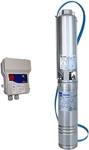
Figure 1: Generic EBARA 4N7A-12 Submersible Pump (V230+BOX variant) showing the pump body and the external control box.

Figure 2: Close-up view of the EBARA 4N7A-12 pump body, highlighting its stainless steel construction and discharge port.
4. Setup and Installation
4.1 Pre-Installation Checks:
- Verify that the power supply (V230) matches the pump's requirements.
- Inspect the pump for any visible damage from shipping.
- Ensure the well or water source is free from large debris that could obstruct the pump.
- Confirm adequate space for vertical or horizontal installation as planned.
4.2 Mechanical Installation:
- Secure the Pump: Attach a strong rope or safety cable to the designated lifting eye on the pump. Do not use the power cable for lifting.
- Connect Discharge Pipe: Connect the appropriate discharge pipe (G2 connection) to the pump's outlet. Ensure a watertight seal using thread sealant tape.
- Lowering the Pump: Carefully lower the pump into the well or water source, ensuring it remains vertical (for vertical installation) or horizontal (for horizontal installation) and does not touch the bottom or sides. Maintain sufficient clearance from the bottom to avoid drawing sediment.
- Check Submersion: Ensure the pump is fully submerged before proceeding with electrical connections.
4.3 Electrical Connection (V230+BOX variant):
The V230+BOX variant includes an external control box. This box typically contains the capacitor and thermal overload protection for the single-phase motor.
- Position the Control Box: Mount the control box in a dry, accessible location, away from direct sunlight and moisture.
- Connect Pump Cable: Connect the pump's power cable to the designated terminals inside the control box, following the wiring diagram provided with the control box. Ensure correct phase, neutral, and ground connections.
- Connect Power Supply: Connect the main power supply (230V AC) to the input terminals of the control box. Install a suitable circuit breaker or fuse for protection.
- Grounding: Ensure the pump and control box are properly grounded to prevent electrical hazards.
- Test: Before final sealing, perform a brief test run to ensure correct rotation and operation.
5. Operating Instructions
5.1 Starting the Pump:
- Ensure the pump is fully submerged and all connections are secure.
- Open any valves in the discharge line to allow water flow.
- Switch on the power supply to the control box. The pump should start immediately.
- Monitor the initial operation for any unusual noises or vibrations.
5.2 Monitoring Operation:
- Regularly check the water flow and pressure to ensure consistent performance.
- Listen for any abnormal sounds, which could indicate issues like cavitation or bearing wear.
- Avoid prolonged dry running, as this can severely damage the pump.
5.3 Shutting Down the Pump:
- Close any discharge line valves if necessary.
- Switch off the power supply to the control box.
- For extended periods of non-use, especially in freezing conditions, consider removing the pump or draining the system to prevent damage.
6. Maintenance
Regular maintenance ensures the longevity and optimal performance of your submersible pump. Always disconnect power before performing any maintenance.
6.1 Routine Checks:
- Visual Inspection: Periodically inspect the pump cable for signs of wear, cuts, or damage.
- Performance Monitoring: Note any changes in flow rate or pressure, which may indicate a blockage or wear.
- Control Box Check: Ensure the control box is clean, dry, and free from insect infestations.
6.2 Cleaning:
If the pump's performance degrades due to sediment buildup, it may need to be retrieved and cleaned. Carefully remove any debris from the intake screen and around the impeller area. Avoid using harsh chemicals that could damage pump components.
6.3 Winterization:
In areas prone to freezing temperatures, it is crucial to protect the pump and piping. If the pump is installed in a shallow well or tank that may freeze, it should be removed, drained, and stored in a frost-free location. Alternatively, ensure the water level remains below the frost line and the system is adequately insulated.
7. Troubleshooting
This section outlines common issues and their potential solutions. For problems not listed here or if solutions do not resolve the issue, contact qualified service personnel.
| Problem | Possible Cause | Solution |
|---|---|---|
| Pump does not start |
|
|
| Low or no water flow |
|
|
| Pump runs continuously |
|
|
8. Specifications
Pump Technical Data:
| Parameter | Value |
|---|---|
| Model | 4N7A-12 |
| Maximum Liquid Temperature | 40°C (dependent on motor temperature) |
| Maximum Sand Content | 50 ppm |
| Maximum Chlorine Content | 500 ppm |
| Discharge Connection | G2 |
| MEI (Minimum Efficiency Index) | > 0.4 |
| Power Supply (V230+BOX variant) | 230V AC |
Materials:
- External Casing, Shaft, Valve: AISI 304 Stainless Steel
- Discharge Port: EN 1.4308 (ASTM CF8)
- Impeller: Ixef (for 4N7 models)
- Diffuser: PPE+PS reinforced with glass fibers
9. Warranty and Support
This product is covered by a standard manufacturer's warranty against defects in materials and workmanship. The warranty period typically begins from the date of purchase. Please retain your proof of purchase for warranty claims.
The warranty does not cover damage caused by improper installation, misuse, neglect, unauthorized modifications, or operation outside the specified parameters.
For technical support, service, or warranty inquiries, please contact your retailer or the manufacturer's customer service department. Contact information can usually be found on the product packaging or the retailer's website.