
1. Introduction
The CEMELI W3230 is a microcomputer high-precision temperature controller designed for various applications requiring accurate temperature regulation. This device features a digital display for both current and set temperatures, along with intuitive controls for easy operation. It is suitable for embedded installation and operates within a wide temperature range.
This manual provides essential information for the safe and effective use of your W3230 temperature controller, including product overview, specifications, setup instructions, operating procedures, maintenance tips, and troubleshooting guidance.
2. Safety Information
- Electrical Safety: Always ensure the power supply matches the controller's specified voltage (110V-220V AC for this model). Incorrect voltage can cause damage or electric shock.
- Professional Installation: Wiring should be performed by qualified personnel to prevent electrical hazards and ensure correct functionality.
- Proper Wiring: Double-check all connections before applying power. Loose or incorrect wiring can lead to malfunction or fire.
- Environmental Conditions: Do not expose the controller to excessive moisture, dust, corrosive gases, or extreme temperatures outside its operating range.
- Load Capacity: Ensure the connected load's current and power do not exceed the controller's relay output specifications. Overloading can damage the device.
- Disconnection: Disconnect power before performing any maintenance, wiring changes, or troubleshooting.
3. Product Overview
The W3230 temperature controller features a compact design with a clear digital display and user-friendly buttons. It includes terminals for power input, temperature sensor, and relay output.

Figure 3.1: Front view of two W3230 temperature controllers, highlighting the digital displays and control buttons.
3.1. Display and Indicators
- PV (Process Value): The upper red digital display shows the current measured temperature.
- SV (Set Value): The lower blue digital display shows the target temperature set by the user.
- OUT Indicator: An LED indicator (usually on the right side of the display) illuminates when the relay output is active (i.e., when power is being supplied to the connected load).
3.2. Control Buttons
- SET Button: Used to enter and exit parameter setting mode.
- Up (▲) Button: Used to increase values or navigate through parameters.
- Down (▼) Button: Used to decrease values or navigate through parameters.
- Restart Button: A small button (often recessed) used to reset the controller.
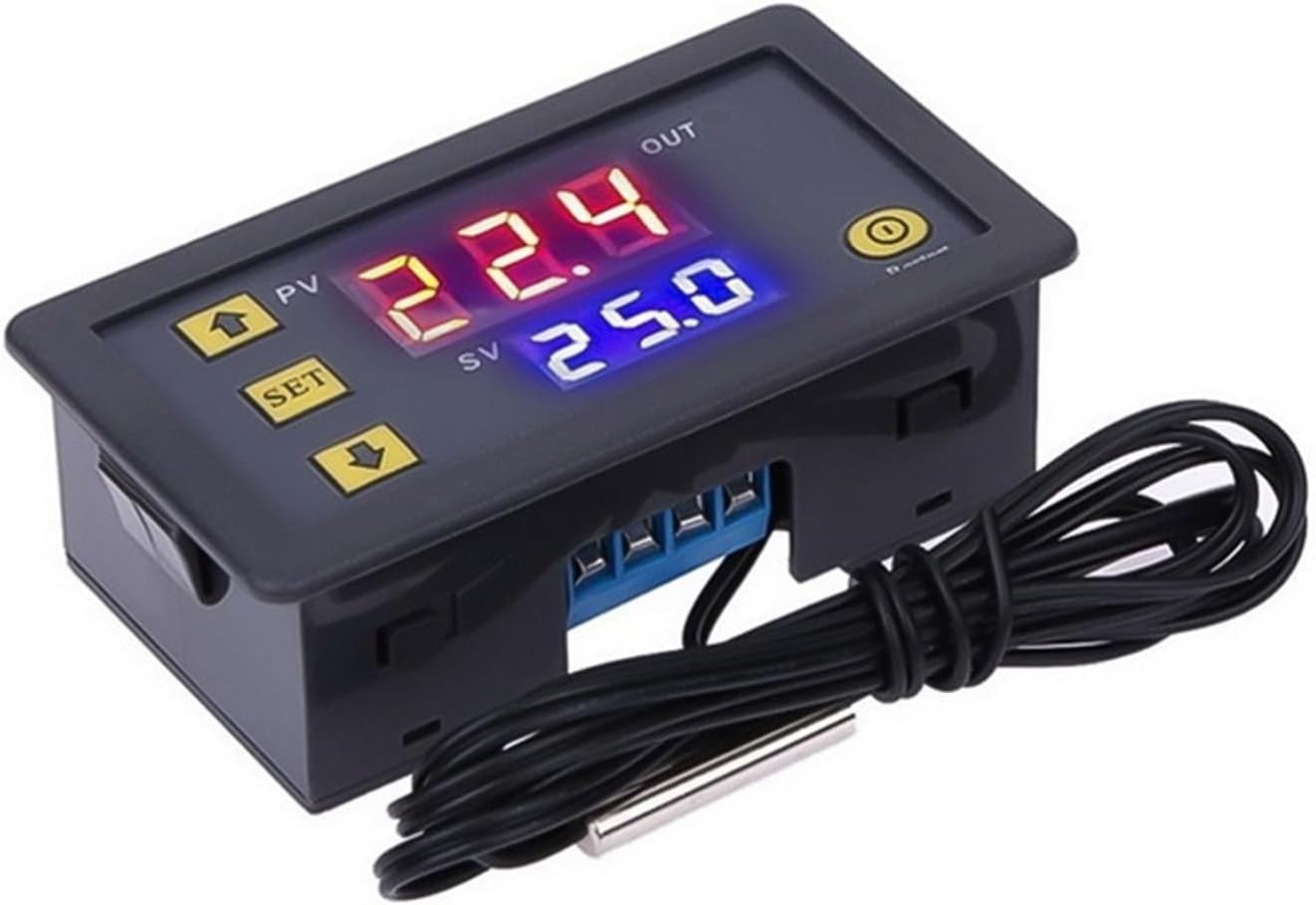
Figure 3.2: Side view of the W3230 controller, illustrating the wiring terminals and the temperature sensor.
4. Specifications
| Feature | Specification |
|---|---|
| Model | W3230 |
| Control Type | Temperature |
| Control Mode | Intelligent Temperature Control Regulator |
| Measurement Object | Temperature |
| Temperature Range | -50℃ to +120℃ |
| Temperature Measurement Error | ±1℃ |
| Opening Size | Standard (for embedded installation) |
| Installation Type | Embedded Installation |
| Output Signal | Standard (Relay Output) |
| Working Voltage | 110V-220V AC |
| Overall Dimensions | 79mm x 43mm x 26mm (approx.) |
| Weight | 44 Grams |
5. Setup
5.1. Mounting
The W3230 controller is designed for embedded installation. Cut an appropriate opening in your panel or enclosure according to the controller's dimensions (approximately 79mm x 43mm). Insert the controller and secure it using the integrated clips or mounting tabs.
5.2. Wiring Instructions
Refer to the wiring diagram usually printed on the side or back of the controller. Ensure all connections are secure and correct before applying power. Incorrect wiring can damage the unit or connected devices.
Figure 5.1: Wiring terminals and sensor connection on the W3230 controller.
- Power Input: Connect the 110V-220V AC power supply to the designated power input terminals (typically marked L and N or AC IN).
- Temperature Sensor: Connect the NTC temperature sensor probe to the sensor input terminals (typically marked SENSOR). Ensure the sensor is placed in the environment where temperature needs to be measured.
- Relay Output: Connect the device you wish to control (e.g., heater, cooler, fan) to the relay output terminals (typically marked OUT or LOAD). Ensure the load's power requirements do not exceed the relay's maximum rating. The relay acts as a switch; you will typically connect one side of your load to the relay and the other side to your power supply, with the relay completing the circuit.
6. Operating Instructions
6.1. Power On
Once wired correctly, apply power to the controller. The PV display will show the current temperature, and the SV display will show the last set target temperature.
6.2. Setting the Target Temperature (SV)
- Press the SET button once. The SV (blue) display will start flashing.
- Use the Up (▲) and Down (▼) buttons to adjust the target temperature to your desired value.
- Press the SET button again to confirm the setting and exit, or wait for approximately 5 seconds for the display to stop flashing and save automatically.
6.3. Advanced Parameter Settings
To access advanced parameters (P0-P6), press and hold the SET button for approximately 3-5 seconds until the display shows "P0". Use the Up (▲) and Down (▼) buttons to navigate through the parameters (P0 to P6). To modify a parameter's value, press SET once, adjust with Up/Down, then press SET again to save. To exit, press and hold SET or wait for auto-exit.
- P0: Heating/Cooling Mode (H/C)
H = Heating Mode: Output turns ON when PV < SV - Hysteresis, turns OFF when PV ≥ SV.
C = Cooling Mode: Output turns ON when PV > SV + Hysteresis, turns OFF when PV ≤ SV. - P1: Hysteresis Setting (0.1-30℃)
This value prevents rapid cycling of the output. For example, if SV is 25℃ and Hysteresis is 2℃ in Heating mode, the output turns ON at 23℃ and OFF at 25℃. - P2: Upper Limit of Set Temperature (SV Max) (-50℃ to 120℃)
Sets the maximum allowable target temperature. - P3: Lower Limit of Set Temperature (SV Min) (-50℃ to 120℃)
Sets the minimum allowable target temperature. - P4: Temperature Correction (-10℃ to 10℃)
Adjusts the measured temperature (PV) to compensate for sensor inaccuracies. PV = Actual Temperature + P4. - P5: Delay Start Time (0-10 minutes)
Sets a delay before the output activates after the condition is met. Useful for protecting compressors in cooling applications. - P6: High Temperature Alarm (0℃ to 120℃)
If the measured temperature (PV) exceeds this value, the display will show "HHH" and an alarm may sound (if applicable).
6.4. Restart Function
Press the small Restart button (often recessed, requiring a pointed object) to reset the controller to its default settings or to clear certain error states.
7. Maintenance
- Cleaning: Wipe the controller's surface with a soft, dry cloth. Do not use abrasive cleaners or solvents. Ensure no liquids enter the device.
- Sensor Care: Keep the temperature sensor probe clean and free from debris. Avoid bending or damaging the sensor cable.
- Regular Checks: Periodically inspect wiring connections for tightness and signs of wear or corrosion.
- Environmental Protection: Ensure the operating environment remains within the specified conditions to prolong the life of the device.
8. Troubleshooting
- No Display / No Power:
Possible Cause: No power supply or incorrect wiring.
Solution: Check power connections, ensure correct voltage (110V-220V AC), and verify wiring according to the diagram. - "LLL" or "HHH" on PV Display:
Possible Cause: Temperature sensor error (open circuit, short circuit, or out of range).
Solution: Check the sensor connection. Replace the sensor if it is damaged. "LLL" indicates temperature below lower limit, "HHH" indicates temperature above upper limit or sensor fault. - "--- " on PV Display:
Possible Cause: High temperature alarm (P6 parameter exceeded).
Solution: Check the actual temperature and the P6 setting. - Output Not Switching (OUT indicator not lighting up):
Possible Cause: Incorrect temperature settings, wrong heating/cooling mode (P0), or relay failure.
Solution: Verify SV and PV values. Check P0 setting. Ensure hysteresis (P1) is appropriate. If all settings are correct, the relay might be faulty. - Inaccurate Temperature Reading:
Possible Cause: Sensor placement, sensor calibration error, or P4 parameter.
Solution: Ensure the sensor is correctly placed and not influenced by external heat sources. Adjust the P4 temperature correction parameter if necessary.
9. Warranty and Support
For warranty information and technical support, please refer to the purchase documentation or contact your seller directly. Keep your proof of purchase for any warranty claims.