
1. Introduction
This manual provides detailed instructions for the installation, operation, and maintenance of your SunnyGator 4-Channel LED RF Controller (Model C). This versatile controller is designed for use with RGBW, RGB, dual-color, or single-color LED light strips, offering precise control over lighting effects. It features 2.4G wireless RF technology, allowing for smooth dimming, color temperature adjustment, and dynamic mode selection.
2. Safety Information
- Ensure the input voltage (12-36VDC) matches the power supply and LED strip requirements. Incorrect voltage can damage the device.
- Do not expose the controller to moisture or extreme temperatures.
- Disconnect power before making any electrical connections or performing maintenance.
- Installation should be performed by a qualified professional if you are unsure about electrical wiring.
- Keep out of reach of children.
3. Product Overview
The SunnyGator 4-Channel LED RF Controller is a constant voltage RF receiver compatible with various RF remote controls. It allows for individual or simultaneous control of multiple lighting zones. Key features include smooth dimming from 0.1% to 100%, 10 built-in dynamic modes, and a 2.4GHz wireless range of up to 30m. It also supports automatic transmission and synchronization functions for extended range and coordinated lighting effects.

Figure 3.1: The 4-channel LED controller shown with various compatible remote controls and a WiFi-Relay module. This image illustrates the range of control options available for the system.
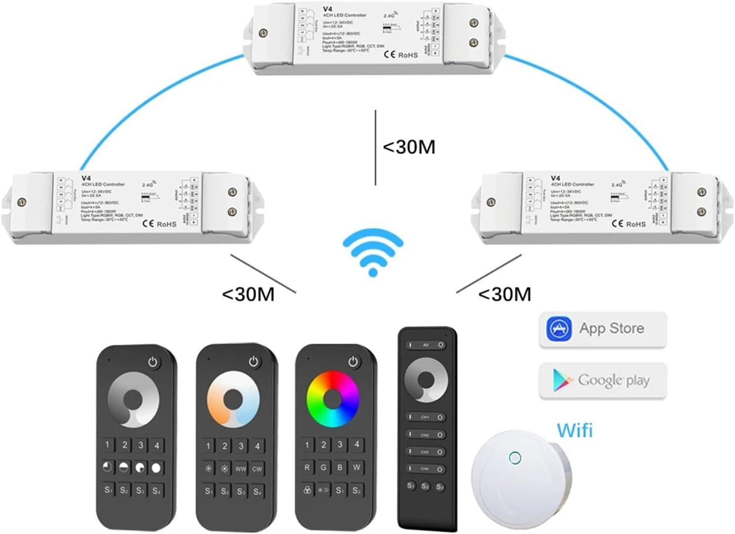
Figure 3.2: A diagram illustrating the wireless connectivity of multiple LED controllers with various remote controls and a central WiFi module. It shows the 30-meter range for direct control and the potential for extended range through automatic transmission between controllers.
4. Technical Specifications

Figure 4.1: Detailed technical parameters and mechanical dimensions of the LED controller. This includes input/output specifications, dimming data, environmental conditions, safety standards, and warranty information.
| Category | Parameter | Value |
|---|---|---|
| Input and Output | Input Voltage | 12-36VDC |
| Input Current | 20.5A | |
| Output Voltage | 4 x (12-36)VDC | |
| Output Current | 4CH, 5A/CH | |
| Output Power | 4 x (60-180)W | |
| Dimming Data | Input Signal | RF 2.4GHz + Push Dim |
| Control Distance | 30m | |
| Dimming Range | 0-100% | |
| Environment | Operation Temperature | Ta: -30°C ~ +55°C |
| IP Rating | IP20 | |
| Warranty & Protection | Warranty | 5 years |
| Protection | Reverse Polarity |
5. Installation
5.1. Mechanical Structure and Wiring
Refer to Figure 5.1 for the physical dimensions and wiring terminals of the controller. Ensure proper connections for input power and LED strip outputs.
Figure 5.1: Diagram showing the mechanical structure, dimensions (175mm x 45mm x 27mm), and wiring terminals of the 4-channel LED controller. Input terminals are on the right (Power Input +, Power Input -), and output terminals are on the left (Output Red LED -, Output Green LED -, Output Blue LED -, Output White LED -, Output LED +).
5.2. Connection Steps
- Power Supply: Connect a 12-36VDC power supply to the "Power Input +" and "Power Input -" terminals on the controller. Observe polarity.
- LED Strip: Connect your RGBW, RGB, CCT, or single-color LED strip(s) to the corresponding output terminals.
- For RGBW strips: Connect R, G, B, W, and common anode (+) to the respective terminals.
- For RGB strips: Connect R, G, B, and common anode (+) to the respective terminals.
- For CCT (dual-color) strips: Connect Warm White (WW), Cold White (CW), and common anode (+) to the appropriate terminals (e.g., W and B for WW/CW, and +).
- For single-color strips: Connect the single color channel and common anode (+) to any available output channel.
- Secure Connections: Ensure all wire connections are secure to prevent shorts or loose contacts.
- Power On: Once all connections are verified, apply power to the controller.
6. Operation
6.1. Remote Control Pairing
To pair a new remote control with the LED controller:
- Ensure the controller is powered on.
- Briefly press the "Match key" button on the controller (located near the input terminals, as shown in Figure 5.1). The LED indicator on the controller will flash.
- Within 5 seconds, press any button on the desired remote control.
- The LED indicator on the controller will stop flashing and remain solid if pairing is successful.
The controller can be paired with up to 10 remote controls.
6.2. Remote Control Functions
The controller is compatible with various RF remote controls. Below are common functions for specific remote models:
LSD-RT6 (4 Zone Dimming Remote)

Figure 6.1: Button layout and functions for the LSD-RT6 (4 Zone Dimming Remote) and LSD-RT7 (4 Zone CCT Remote).
- Power Button: Short press to turn on/off zone light.
- Brightness Ring: Touch to change current zone brightness.
- Zone Select (1, 2, 3, 4): Short press to select and turn on a zone light. Long press (2s) to turn off a zone light. Short press multiple zone keys quickly to select multiple zones synchronously.
- Brightness Presets (25%, 50%, 75%, 100%): Short press to set brightness for the current selected zone.
- Scene Recall/Save (S1, S2, S3, S4): Short press to recall a scene. Long press (2s) to save the current state into S1/S2/S3/S4. 4 zone recall or save synchronously.
LSD-RT7 (4 Zone CCT Remote)
Refer to Figure 6.1 for button layout.
- Power Button: Short press to turn on/off zone light.
- Color Temperature Ring: Touch to change current zone color temperature.
- Zone Select (1, 2, 3, 4): Short press to select and turn on a zone light. Long press (2s) to turn off a zone light. Short press multiple zone keys quickly to select multiple zones synchronously.
- Brightness Adjust (*): Short press to adjust brightness for the current selected zone (10 levels). Long press (1-6s) for continuous 256 levels adjustment.
- Warm White (WW) / Cold White (CW): Short press to get warm white or cold white directly for the current selected zone.
- Scene Recall/Save (S1, S2, S3, S4): Short press to recall a scene. Long press (2s) to save the current state into S1/S2/S3/S4. 4 zone recall or save synchronously.
LSD-RT9 (4 Zone RGB/RGBW Remote)

Figure 6.2: Button layout and functions for the LSD-RT9 (4 Zone RGB/RGBW Remote).
- Power Button: Short press to turn on/off all zone lights.
- Color Ring: Touch to change current zone static RGB color.
- Zone Select (1, 2, 3, 4): Short press to select and turn on a zone light. Long press (2s) to turn off a zone light. Short press multiple zone keys quickly to select multiple zones synchronously.
- RGB Buttons (R, G, B): Short press to get red, green, or blue color directly. Long press (1-6s) to adjust R/G/B brightness continuously.
- White (W) Button:
- For RGB light: Short press to turn on/off white (RGB mix). Long press (1-6s) to adjust saturation continuously (change current static RGB color to mixed white slowly).
- For RGBW light: Short press to turn on/off W channel. Long press (1-6s) to adjust W brightness continuously (change saturation by adding white color slowly).
- Dynamic Mode Select: Short press to adjust dynamic mode for the current selected zone. Short press next dynamic mode. Long press (2s) to run mode-cycle.
- Brightness/Speed Adjust:
- For static color: Short press for 10 levels adjustment. Long press (1-6s) for continuous 256 levels adjustment.
- For dynamic mode: Adjust speed. Short press for 10 levels adjustment. Long press (2s) to get the default speed.
- Scene Recall/Save (S1, S2): Short press to recall a scene. Long press (2s) to save the current state into S1/S2. 4 zone recall or save synchronously.
6.3. Advanced Features
- Automatic Transmission Function: One receiver can transmit the remote control signal to another receiver within 15m. This extends the effective remote control distance beyond 100m.
- Automatic Synchronization Function: When controlled by the same remote, different receivers can work synchronously, maintaining the same dynamic mode and speed.
- WiFi Control (SkySmart App): The controller can be used with a WiFi-Relay module for control via the SkySmart APP on iOS or Android devices. This allows for brightness, color temperature, RGB, RGBW, and RGB+CCT adjustments.

Figure 6.3: The WiFi-Relay module, which converts Wi-Fi signals to RF signals, enabling control via the SkySmart App. Examples of the app interface for brightness, color temperature, and RGB control are shown.
7. Maintenance
- Cleaning: Use a soft, dry cloth to clean the controller and remote controls. Do not use abrasive cleaners or solvents.
- Environment: Ensure the controller is kept in a dry environment, away from direct sunlight and extreme temperatures, to prolong its lifespan.
- Battery Replacement (Remotes): If remote control responsiveness decreases, replace the batteries according to the remote's specific instructions (typically coin cell batteries).
8. Troubleshooting
| Problem | Possible Cause | Solution |
|---|---|---|
| LED strip does not light up. | No power to controller, incorrect wiring, faulty LED strip. | Check power supply connection. Verify input/output wiring polarity. Test LED strip with another power source if possible. |
| Remote control not responding. | Remote not paired, dead battery, out of range. | Re-pair the remote control (Section 6.1). Replace remote battery. Ensure remote is within 30m of the controller. |
| Lights flicker or behave erratically. | Loose connections, insufficient power supply, interference. | Check all wiring connections. Ensure power supply meets the total wattage requirements of the LED strips. Minimize RF interference from other devices. |
| Cannot control via SkySmart App. | WiFi-Relay not connected/configured, app issues. | Ensure WiFi-Relay is properly installed and connected to your network. Check app settings and ensure it's linked to the WiFi-Relay. |
9. Warranty and Support
The SunnyGator 4-Channel LED RF Controller (Model C) comes with a 5-year warranty against manufacturing defects. This warranty covers normal use and proper installation as described in this manual.
For technical support, troubleshooting assistance, or warranty claims, please contact SunnyGator customer service through your purchase platform or the official SunnyGator website. Please have your product model and purchase date available when contacting support.