1. Introduction
The GODIAG ECU GPT Boot AD Connector is a specialized adapter designed to facilitate the reading and writing of Engine Control Unit (ECU) data. This tool is particularly useful for automotive diagnostics and programming, offering compatibility with various J2534 devices such as Openport, PCMFlash, and FC200. It provides flexible connection methods, including direct ECU terminal wiring and OBD2 emulation, enabling data access even for ECUs that typically require cover removal.
2. Product Overview
The GODIAG ECU GPT Boot AD Connector serves as an interface for advanced ECU programming tasks. It addresses the challenge of diverse ECU connection methods and regional variations in read/write procedures. This adapter allows for both "open cap" connections, where the ECU cover is removed for direct access, and "without opening the cover" methods, by emulating the standard OBD2 diagnostic interface. Its design aims to simplify complex ECU data operations for technicians and enthusiasts.
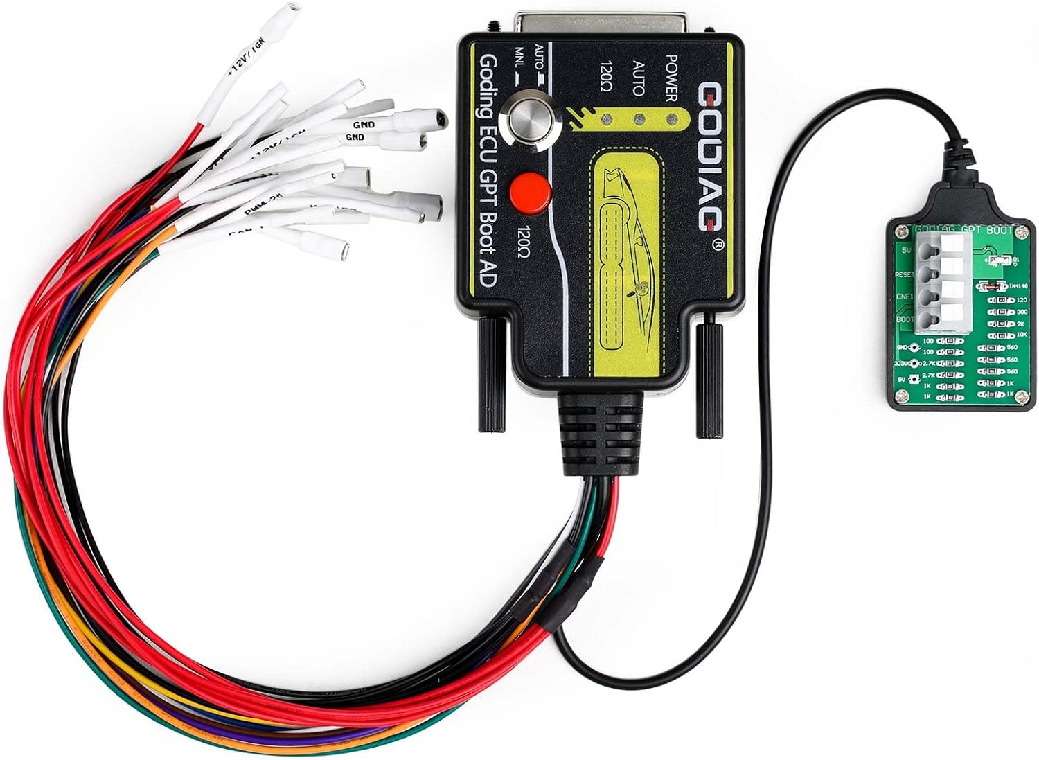
Figure 2.1: The GODIAG ECU GPT Boot AD Connector with its various wiring harnesses. This image displays the main adapter unit connected to a smaller boot board and a bundle of colored wires for direct ECU connections, along with an OBD2 to DB25 cable.
3. Key Features
- Supports standard OBD2 protocol equipment for diagnostic functions.
- Enables ECU data reading and writing.
- Compatible with J2534 devices, including Scanmatik 2 PRO, OpenPort 2.0, Mongoose JLR, MongoosePro JLR, Teradyne GNA600 (VCM 1), and Mazda VCM 2.
- Specifically, Scanmatik 2 PRO for PCMflash can form GPT1 and GPT2 signals for Module 71 operations.
- Allows for ECU terminal wiring based on manufacturer-specific diagrams.
- Supports both "open cap" and "without opening the cover" ECU read/write methods.
- Emulates the standard OBD2 diagnostic interface for versatile connectivity.
- Features an ECU dedicated connection terminal.
- Supports manual ignition power control.
- The ECU interface cable is clearly labeled for ease of use.
- Supports ECU conversion to OBD2 mode for data reading and writing.
- Supports various signals: RESET, BOOT, CNF1, GPT1, GPT2, 5V, 3.3V, VPP, GND.
- Supports PCMFlash automatic control of ignition power supply.
- Equipped with a switch for freely selecting the 120Ω CANbus resistor.
- Supports GPT for reading and writing data without disassembling the ECU.
- Includes a BOOT resistance board connecting cable with an anti-lost resistor design.

Figure 3.1: Visual representation of the GODIAG ECU GPT Boot AD Adapter's main features, highlighting its capabilities for ECU connection, power control, and various signal support.
4. Package Contents
Upon unboxing, please verify that all the following components are present and in good condition:
- 1x GODIAG ECU GPT Boot AD Programming Adapter
- 1x OBD2 to DB25 Cable
- 8x Soft Silicone Wires

Figure 4.1: All components included in the GODIAG ECU GPT Boot AD Connector package, showing the main adapter, the OBD2 to DB25 cable, and the set of soft silicone wires.
5. Setup Guide
Setting up the GODIAG ECU GPT Boot AD Connector involves connecting it to the target ECU and your J2534 compatible device. The connection method will depend on the specific ECU and the desired operation (e.g., OBD2, BOOT, GPT).
5.1. Connecting the Main Adapter
The main GODIAG adapter unit serves as the central hub for all connections. It features a DB25 port for connecting the OBD2 cable or the individual silicone wires.

Figure 5.1: An alternative view of the GODIAG ECU GPT Boot AD Connector, illustrating the various connection points and the overall compact design of the device.
5.2. OBD2 to DB25 Cable Connection
For ECUs that support OBD2 communication for reading/writing, use the provided OBD2 to DB25 cable. Connect the DB25 end to the main GODIAG adapter and the OBD2 end to the vehicle's OBD2 port or a compatible bench harness.
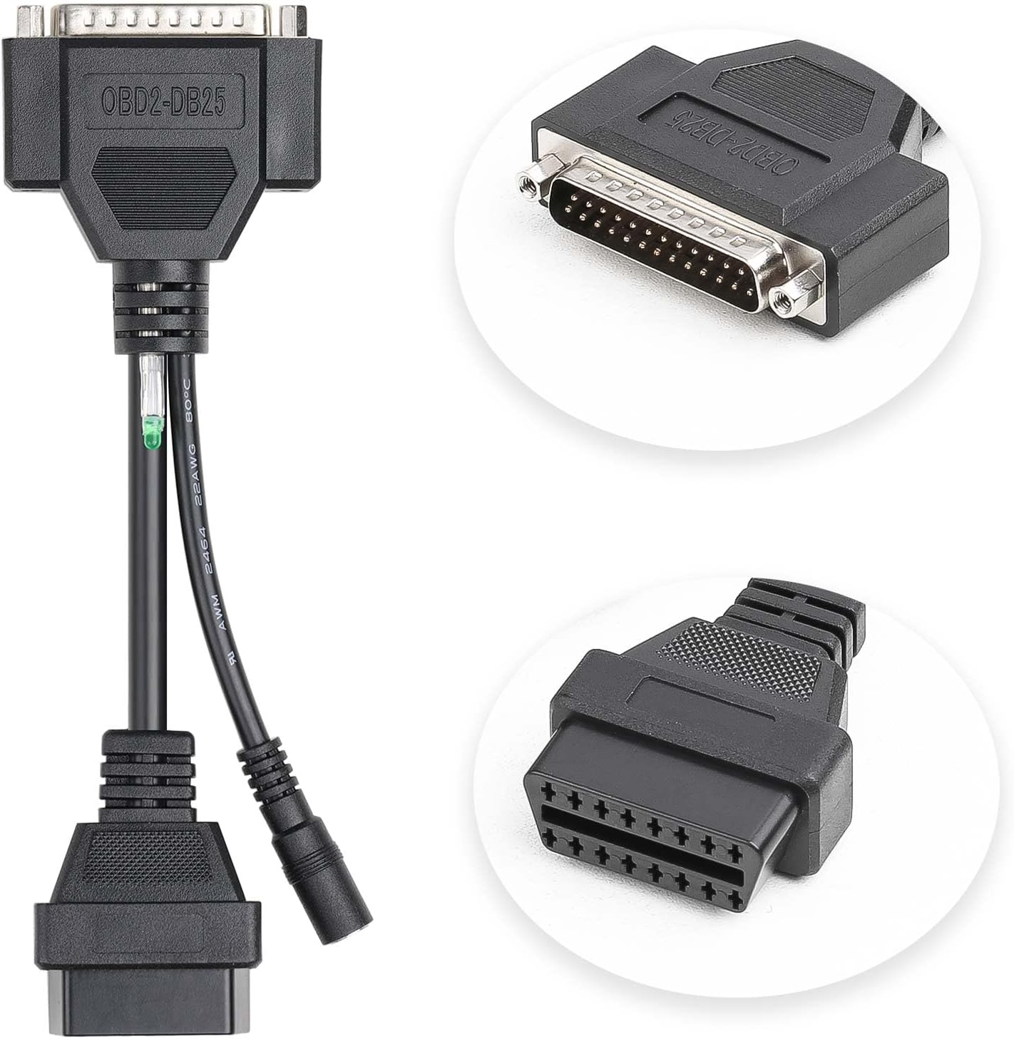
Figure 5.2: Close-up view of the OBD2 to DB25 cable, showing its distinct connectors for interfacing with the GODIAG adapter and the vehicle's diagnostic port.
5.3. Direct ECU Terminal Wiring (Boot/GPT Mode)
For ECUs requiring direct connection (e.g., in Boot or GPT mode, often requiring the ECU cover to be opened), use the soft silicone wires. These wires connect to the DB25 port on the main adapter and are then individually wired to specific pins on the ECU. Refer to the ECU's specific wiring diagrams for correct pin assignments. The small green boot board is used for specific boot mode connections.

Figure 5.3: The reverse side of the GODIAG ECU GPT Boot AD Connector, displaying manufacturer information and a QR code, which may link to additional resources or wiring diagrams.
Important: Always consult the specific ECU's technical documentation or a reliable database for accurate pinouts and connection procedures before attempting direct wiring. Incorrect connections can damage the ECU or the adapter.
6. Operating Instructions
The GODIAG ECU GPT Boot AD Connector works in conjunction with J2534 compatible software and hardware. The operational steps will largely depend on the specific J2534 device and the ECU programming software you are using (e.g., PCMFlash).
6.1. General Operation Flow
- Identify ECU Type: Determine if the ECU requires OBD2, Boot, or GPT mode for reading/writing. This will dictate the connection method.
- Connect Hardware:
- For OBD2: Connect the OBD2 to DB25 cable to the GODIAG adapter and then to the ECU (via vehicle OBD port or bench harness).
- For Boot/GPT: Use the soft silicone wires to connect the GODIAG adapter to the specific ECU pins as per the ECU's wiring diagram. Ensure proper power and ground connections.
- Connect J2534 Device: Connect your J2534 compatible device (e.g., Scanmatik 2 PRO, OpenPort 2.0) to your computer and to the GODIAG adapter (if applicable, some J2534 devices connect directly to the OBD2 port, and the GODIAG adapter is inline).
- Launch Software: Open your ECU programming software (e.g., PCMFlash).
- Select Protocol/Module: Within the software, select the appropriate ECU protocol or module (e.g., Module 71 for GPT, or specific Boot modes).
- Initiate Read/Write: Follow the software's instructions to initiate the ECU data reading or writing process.
- Monitor Progress: Observe the software's progress indicators and any status lights on the GODIAG adapter.
- Disconnect Safely: Once the operation is complete and verified, safely disconnect the hardware in reverse order of connection.
6.2. Specific Considerations
- GPT Signals: For operations requiring GPT1 and GPT2 signals (e.g., PCMflash Module 71), ensure your J2534 device (like Scanmatik 2 PRO) is capable of forming these signals.
- 120Ω Resistor: Utilize the built-in switch on the GODIAG adapter to freely select the 120Ω CANbus resistor as required by the ECU or software.
- Ignition Power Control: The adapter supports manual and PCMFlash automatic control of ignition power supply, which is crucial for certain ECU operations.

Figure 6.1: An illustrative diagram showing various ECU connection scenarios, including OBD2 Bench, GPT Bench (no disassembly), Boot CNF1 Read ECU, and Simple Boot resistance board, all facilitated by the GODIAG adapter.
7. Maintenance
Proper maintenance ensures the longevity and reliable performance of your GODIAG ECU GPT Boot AD Connector.
- Cleaning: Use a soft, dry cloth to wipe the adapter and cables. Avoid using harsh chemicals or abrasive materials.
- Storage: Store the device and its components in a clean, dry environment, away from direct sunlight, extreme temperatures, and excessive humidity.
- Cable Care: Avoid bending or kinking the cables sharply. Store them neatly to prevent damage to the internal wires.
- Connector Inspection: Periodically inspect the connectors (DB25, OBD2, and wire terminals) for any signs of damage, corrosion, or bent pins.
8. Troubleshooting
If you encounter issues while using the GODIAG ECU GPT Boot AD Connector, consider the following troubleshooting steps:
- No Communication:
- Verify all cable connections are secure and correctly seated.
- Ensure the ECU is properly powered and grounded.
- Check the J2534 device's connection to the computer and its drivers.
- Confirm the correct protocol or module is selected in your ECU programming software.
- If using direct wiring, double-check all pin assignments against the ECU's wiring diagram.
- Read/Write Errors:
- Ensure the ECU is in the correct mode (Boot, GPT, etc.) for the operation.
- Verify that your J2534 device and software support the specific ECU and operation you are attempting.
- Check for sufficient power supply to the ECU during the operation.
- Some ECUs have security features (e.g., TPROT) that may require specific bypass procedures not directly related to the adapter. Consult your software's documentation.
- Adapter Not Recognized:
- Ensure the GODIAG adapter is correctly connected to your J2534 device.
- Verify that your J2534 device's software and drivers are up to date.
For persistent issues, refer to the documentation of your J2534 device and ECU programming software, or contact GODIAG customer support.
9. Specifications
| Attribute | Detail |
|---|---|
| Brand | GODIAG |
| Model Number | SO676 |
| Item Weight | 10.8 ounces |
| Package Dimensions | 6.61 x 4.57 x 2.32 inches |
| Manufacturer Part Number | SO676 |
| ASIN | B0CRTMXP8D |
| UPC | 889327072590 |
| First Available | January 9, 2024 |
10. Warranty and Support
10.1. Warranty Information
Specific warranty terms for the GODIAG ECU GPT Boot AD Connector are provided by the manufacturer. Please refer to the documentation included with your purchase or visit the official GODIAG website for detailed warranty information and registration procedures.
10.2. Customer Support
For technical assistance, product inquiries, or support, please contact GODIAG directly:
- Email: Sales@GoDiag.com
- Website: www.godig.com
When contacting support, please have your product model number (SO676) and purchase details ready.


