
1. Introduction
This manual provides detailed instructions for the installation, operation, and maintenance of the Luejnbogty XKC-Y26-V Non-Contact Liquid Level Sensor. This advanced sensor utilizes signal processing technology to detect liquid levels in sealed non-metallic containers without direct contact with the liquid. It is designed for a wide range of applications, offering ease of installation and reliable performance.
2. Safety Information
- Ensure the input voltage (DC 5-24V) is within the specified range to prevent damage to the sensor.
- Do not attempt to disassemble or modify the sensor, as this may void the warranty and cause malfunction.
- Install the sensor in a dry environment, avoiding direct exposure to extreme temperatures or corrosive substances beyond its operating specifications.
- Always disconnect power before performing any installation, wiring, or maintenance procedures.
- This device is intended for non-contact liquid level detection in non-metallic containers only.
3. Product Overview
The XKC-Y26-V is an intelligent non-contact liquid level detector. It features advanced signal processing and a high-speed chip to accurately detect liquid levels through non-metallic container walls. Its design ensures it is not affected by strong acids, alkalis, or other corrosive liquids, nor by incrustation or impurities within the container.
Key Features:
- Non-contact detection: No direct contact with liquid, suitable for various liquid types and container materials.
- Wide voltage input: Operates on DC 5-24V.
- High and Low Level output signal.
- Intelligent level adjustment and memory function.
- Can realize multi-point series connection.
- IP65 waterproof performance.
Product Components:

Figure 3.1: The XKC-Y26-V Non-Contact Liquid Level Sensor. This image displays the compact white sensor unit connected to a black cable, terminating in a white connector. A small red indicator light is visible on the sensor's surface.
The sensor consists of a main detection unit, an integrated cable, and a connector for power and signal output. A small LED indicator on the unit provides status feedback.
4. Setup and Installation
The XKC-Y26-V sensor is designed for easy installation on the exterior of non-metallic containers. No drilling or direct contact with the liquid is required.
4.1 Mounting the Sensor
- Identify the desired detection point on the non-metallic container (e.g., plastic, glass, ceramic). The sensor can be used for both high and low-level detection.
- Clean the exterior surface of the container where the sensor will be mounted to ensure good adhesion or contact.
- Attach the sensor to the outer wall of the container. The sensor's induction sheet should cling firmly to the pipe or tank wall. Common methods include using adhesive, brackets, or cable ties.

Figure 4.1: The XKC-Y26-V sensor mounted on the exterior of a white PVC pipe using a black cable tie. This demonstrates a typical installation scenario for liquid level detection.
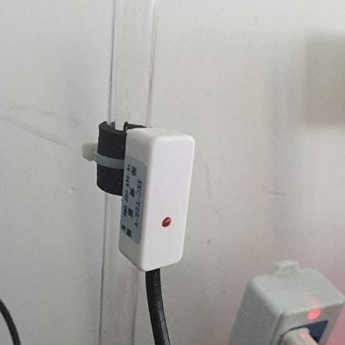
Figure 4.2: The XKC-Y26-V sensor attached to a clear plastic tube, showing its application in transparent containers. The red indicator light on the sensor is illuminated.
4.2 Wiring Instructions
Refer to the wiring diagram below for proper connection. Ensure power is off before connecting wires.

Figure 4.3: Wiring diagram for the XKC-Y26-V sensor, showing connections for power (brown: DC 5-24V positive, blue: GND negative), signal output (yellow), and positive/reverse output selection (black). The diagram also illustrates the sensor's placement relative to the liquid level and the sensitivity adjustment knob.
- Brown Wire: Power Positive (DC 5-24V)
- Blue Wire: GND (Power Supply Negative Pole)
- Yellow Wire: Signal Output (High and Low Level)
- Black Wire: Positive and Reverse Output Selection (Consult specific application requirements for this connection)
5. Operating Instructions
Once properly installed and wired, the XKC-Y26-V sensor operates automatically to detect liquid levels.
5.1 Liquid Level Detection
The sensor detects the presence or absence of liquid at its mounted position. When liquid is present at the sensing point, the output signal will change accordingly (e.g., to a high level). When the liquid level drops below the sensing point, the output signal will revert (e.g., to a low level).
5.2 Sensitivity Adjustment
The sensor features a sensitivity adjustment knob (refer to Figure 4.3) which can be used to fine-tune its detection capabilities based on container wall thickness and material. Turning the knob allows for adjustment of the detection threshold. The induced liquid level height is related to the sensitivity of the sensor; higher sensitivity generally means a lower induced liquid level is detected.
5.3 Output Signal Interpretation
The sensor provides a High and Low Level output signal. The specific voltage levels for 'High' and 'Low' correspond to the input voltage (Vin) and 0V respectively. This signal can be connected to a microcontroller, relay, or other control system to trigger actions based on the detected liquid level.
6. Maintenance
Due to its non-contact nature, the XKC-Y26-V sensor requires minimal maintenance.
- Cleaning: Periodically inspect the exterior of the sensor and the container wall at the sensing point. If dust or debris accumulates, gently wipe it clean with a soft, dry cloth. Avoid using harsh chemicals or abrasive materials.
- Environmental Conditions: Ensure the sensor remains within its specified working environment temperature (0-85 Celsius) and humidity (5%-100%).
- Cable Integrity: Regularly check the sensor cable for any signs of damage, fraying, or loose connections.
7. Troubleshooting
If the sensor is not functioning as expected, consider the following troubleshooting steps:
- No Detection or Incorrect Readings:
- Verify that the sensor is correctly powered (DC 5-24V).
- Check all wiring connections for proper polarity and secure contact.
- Ensure the sensor is firmly attached to the container wall and there are no gaps or air bubbles between the sensor and the surface.
- Adjust the sensitivity knob. The optimal sensitivity may vary depending on the container material and wall thickness.
- Confirm the container material is non-metallic. The sensor is not designed for metallic containers.
- Check the container wall thickness against the sensor's specifications (refer to Section 8). Excessive thickness can reduce detection capability.
- Intermittent Detection:
- Ensure the sensor is stable and not vibrating.
- Re-check sensitivity settings.
- Inspect for any external interference sources (e.g., strong electromagnetic fields).
- No Output Signal:
- Confirm power supply is active and connected correctly.
- Test the output wire connection to your control system.
8. Specifications
| Product Model | XKC-Y26-V |
| Input Voltage (Vin) | DC 5-24V |
| Output Signal | High and Low Level |
| Current Consumption | 5mA |
| Output Voltage (High Level) | Vin |
| Output Voltage (Low Level) | 0V |
| Output Current | 1-100mA |
| Response Time | 500mS |
| Working Environment Temperature | 0-85 Celsius |
| Humidity | 5%-100% |
| Waterproof Performance | IP65 |
| Applicable Pipe Diameter Range | ≥ 10mm |
| Level Error | +/-1.5mm |
| Dimensions | 18 x 13 x 11mm (Sensor Unit) |
| Cable Length | 45cm |
| Material | ABS (Housing), Copper (Internal) |
Sensitivity vs. Wall Thickness:
| Pipe Outer Diameter D (mm) | Sensing Wall Thickness L (mm) |
| D ≤ 100 | 20 +/- 2 |
| 100 > D ≥ 80 | 15 +/- 2 |
| 80 > D ≥ 60 | 12 +/- 2 |
| 60 > D ≥ 40 | 7 +/- 1 |
| 40 > D ≥ 30 | 5 +/- 1 |
| 30 > D ≥ 20 | 3 +/- 1 |
| 20 > D ≥ 10 | 1.5 +/- 0.5 |
9. Warranty and Support
For warranty information and technical support, please contact the retailer or manufacturer directly. Keep your purchase receipt as proof of purchase. Specific warranty terms and conditions may vary.
For further assistance or inquiries, refer to the contact information provided with your purchase or visit the official Luejnbogty website.