1. Introduction
Thank you for choosing the BSIDE U1 Mini Digital Open Jaw Clamp Multimeter. This device is a compact, intelligent, and versatile tool designed for electrical measurements. It combines the functions of a clamp meter, smart multimeter, and voltage detector, making it suitable for both beginners and professionals. This manual provides essential information for safe and effective operation.
2. Safety Information
Always adhere to safety precautions when using electrical testing equipment. Failure to do so may result in electric shock, injury, or damage to the device or equipment under test.
- Do not exceed the maximum input values specified for each measurement range.
- Ensure the test leads are in good condition and properly connected before any measurement.
- Do not use the device if it appears damaged or is not operating correctly.
- Exercise extreme caution when working with voltages above 30V AC RMS, 42V peak, or 60V DC. These voltages pose a shock hazard.
- Always disconnect power to the circuit before making resistance, continuity, or capacitance measurements.
- The device complies with CE standards and CATIII 600V safety regulations.
3. Package Contents
Verify that all items listed below are present in your package. If any items are missing or damaged, please contact customer service.
- BSIDE U1 Open Jaw Clamp Multimeter
- Test Leads (Red and Black)
- USB Charging Cable
- Carrying Case
- English User Manual (PDF in Spanish available via email)
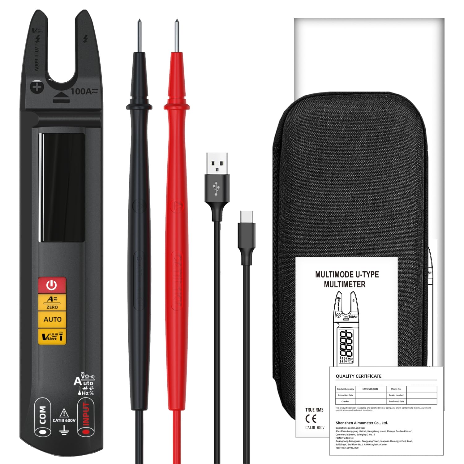
Image 3.1: Contents of the BSIDE U1 package, including the multimeter, test leads, charging cable, and carrying case.
4. Product Overview
The BSIDE U1 features a large color LCD display for clear readings and intuitive controls. It is designed for ease of use and portability.

Image 4.1: Front view of the BSIDE U1 multimeter, highlighting its display, function buttons, and open jaw design.
4.1. Key Features
- 3-in-1 Functionality: Clamp meter, smart multimeter, and voltage detector.
- Auto-Ranging: Automatically selects the correct measurement range.
- Dual Test Mode: Automatic and manual modes for various measurements.
- Large Color LCD: High-precision values with large digits, auto-power off symbol, and low battery indication.
- Safety: Anti-burn and overload protection, CATIII 600V rated.
- Convenience: Built-in LED flashlight, rechargeable Li-ion battery, and compact design.
5. Setup
5.1. Charging the Battery
The BSIDE U1 is powered by a built-in 3.7V rechargeable Li-ion battery. Before first use, or when the low battery indicator appears, charge the device using the provided USB charging cable.
- Connect the small end of the USB charging cable to the charging port on the multimeter.
- Connect the standard USB end to a USB power adapter (not supplied) or a computer USB port.
- The display will indicate charging status. Ensure the device is fully charged for optimal performance.

Image 5.1: The BSIDE U1 multimeter connected to its charging cable, illustrating the rechargeable battery feature.
5.2. Connecting Test Leads
For voltage, resistance, continuity, capacitance, diode, and frequency measurements, connect the test leads to the input jacks.
- Insert the black test lead into the 'COM' (common) jack.
- Insert the red test lead into the 'INPUT' jack.
6. Operating Modes and Measurements
The BSIDE U1 features automatic measurement for common parameters upon power-on. Manual mode allows selection of specific functions.
6.1. Power On/Off
Press and hold the power button (U) to turn the device on or off. The device will automatically enter auto-ranging mode upon startup.
6.2. Automatic Measurement Mode
When powered on, the multimeter automatically detects and measures AC/DC voltage, resistance, and continuity. Simply connect the test leads to the circuit or component, and the device will display the appropriate reading.
6.3. Manual Mode Selection
Press the 'AUTO' button to cycle through manual measurement functions. The selected function will be indicated on the display.
6.4. AC/DC Voltage Measurement
- Ensure test leads are connected correctly (black to COM, red to INPUT).
- Select Voltage mode (if not in auto-ranging).
- Connect the test leads in parallel across the component or circuit to measure voltage.
6.5. AC/DC Current Measurement (Open Jaw Clamp)
The open jaw clamp allows for non-contact AC or DC current measurement. For DC current, a zeroing step is required.
- Select Current mode.
- For DC current, press the 'ZERO' button to zero the reading before measurement.
- Place the open jaw around a single conductor (not a cable containing multiple conductors) through which the current flows.
- Read the current value on the display.

Image 6.1: The BSIDE U1 multimeter being used to measure current in an automotive maintenance scenario.
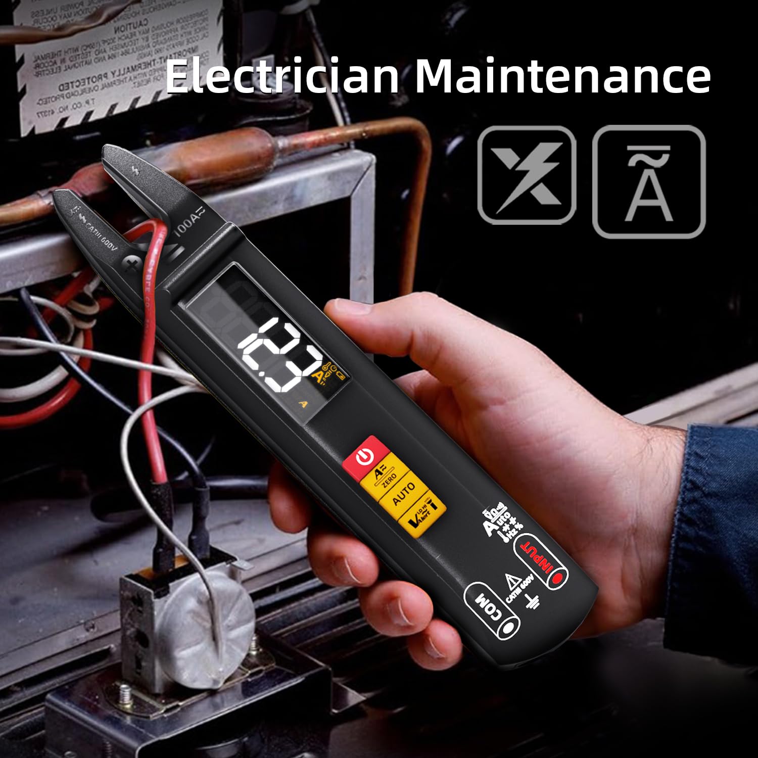
Image 6.2: The BSIDE U1 multimeter measuring current in an electrician maintenance application.
6.6. Resistance Measurement
- Ensure the circuit or component is de-energized.
- Select Resistance mode.
- Connect the test leads across the component to measure its resistance.
6.7. Continuity Test
- Ensure the circuit or component is de-energized.
- Select Continuity mode.
- Connect the test leads across the circuit or component. A continuous beep indicates continuity (low resistance).
6.8. Capacitance Measurement
- Ensure the capacitor is discharged before testing.
- Select Capacitance mode.
- Connect the test leads across the capacitor terminals.

Image 6.3: The BSIDE U1 multimeter performing a capacitance measurement on an electronic circuit board.
6.9. Diode Test
- Ensure the diode is disconnected from the circuit.
- Select Diode mode.
- Connect the red test lead to the anode and the black test lead to the cathode. The forward voltage drop will be displayed. Reverse the leads to check for open circuit.
6.10. Frequency Measurement
- Select Frequency mode.
- Connect the test leads to the signal source.
6.11. NCV (Non-Contact Voltage) Detection
The NCV function allows for quick detection of AC voltage without direct contact.
- Select NCV mode.
- Bring the tip of the multimeter near the conductor. The device will beep and the display will indicate the presence of AC voltage.

Image 6.4: The BSIDE U1 multimeter detecting non-contact voltage (NCV) near an electrical panel, indicated by visual and audible alerts.
6.12. Live Wire Detection
This function helps identify live wires using a single test lead.
- Select Live Wire mode.
- Insert the red test lead into the 'INPUT' jack.
- Touch the tip of the red test lead to the conductor. The device will indicate if the wire is live.
6.13. Ambient Temperature Measurement
The device can measure ambient temperature.
- Select Temperature mode.
- The ambient temperature will be displayed. Note: External thermocouples for contact temperature measurement are not supplied.
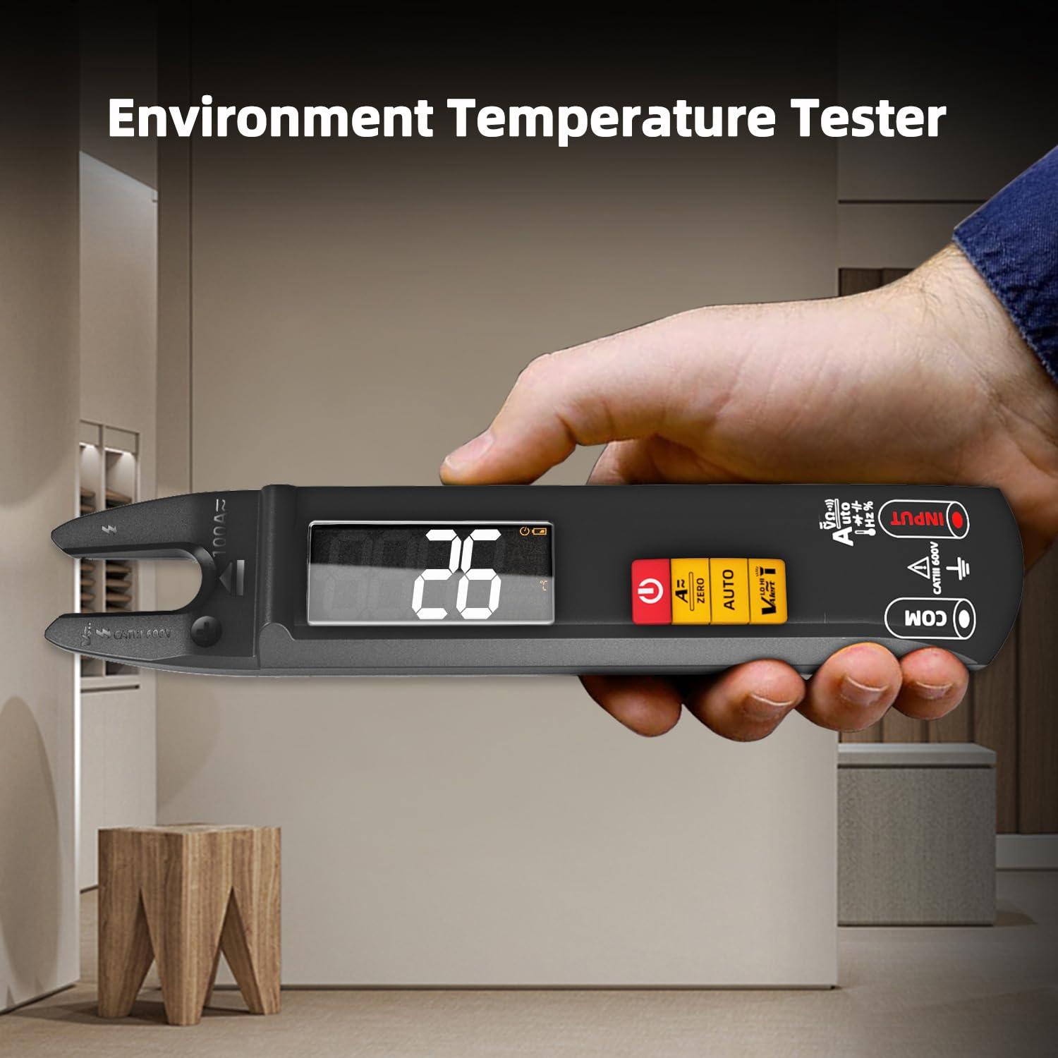
Image 6.5: The BSIDE U1 multimeter displaying the ambient temperature reading.
6.14. LED Flashlight
Press the flashlight button to activate the built-in LED flashlight for illumination in dimly lit areas.
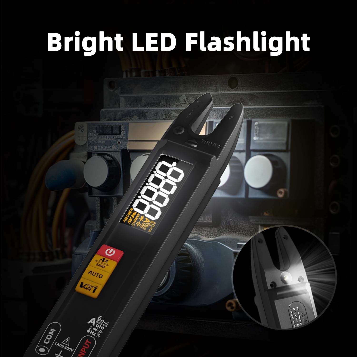
Image 6.6: The BSIDE U1 multimeter with its bright LED flashlight activated, useful for working in dark environments.
7. Maintenance
7.1. Cleaning
Wipe the device with a dry, soft cloth. Do not use abrasive cleaners or solvents. Ensure the device is off and disconnected from any power source before cleaning.
7.2. Battery Care
The integrated Li-ion battery should be charged regularly, especially if the device is not used for extended periods, to maintain battery health. Avoid extreme temperatures during storage.
7.3. Storage
Store the multimeter in its carrying case in a cool, dry place, away from direct sunlight and extreme temperatures. Remove test leads before storing.
8. Troubleshooting
- Device does not power on: Ensure the battery is charged. Connect the USB charging cable and try again.
- Inaccurate readings: Check test lead connections. Ensure the correct measurement mode is selected. For DC current, perform a zeroing operation.
- No continuity beep: Ensure the circuit is de-energized. Check for open circuits or high resistance.
- NCV not detecting voltage: Ensure the NCV sensor is close enough to the conductor. Verify the conductor is live.
If issues persist, refer to the full user manual or contact customer support.
9. Specifications
| Parameter | Range / Value | Accuracy |
|---|---|---|
| Display | 6000 counts | N/A |
| DC Voltage | 0.001-610V | ±(0.8%+3) |
| AC Voltage | 0.050-610V | ±(1.0%+3) |
| DC Current | 1-100A | ±(2.5%+5) |
| AC Current | 1-100A (40-1000 Hz) | ±(2.5%+5) |
| Resistance | 0.1Ω-60MΩ | ±(1.2%+3) |
| Capacitance | 0.010uF-60mF | ±(3.5%+8) |
| Frequency | 1-9.999MHz | ±(2.0%+10) |
| V Alert (NCV) | Up to 1000V AC | N/A |
| Diode Test | Forward voltage drop < 3V | N/A |
| Ambient Temperature | 0-50℃ | ±2℃ |
| Power Supply | 3.7V Rechargeable Li-ion Battery | N/A |
| Dimensions | 192 x 36 x 30 mm | N/A |
| Weight | 102g | N/A |
| Safety Rating | CATIII 600V, CE | N/A |
10. Warranty and Support
For detailed warranty information, please refer to the product packaging or contact your retailer. For technical support or inquiries, BSIDE offers 24/7 customer service. A PDF version of this manual in Spanish is available via email upon request.
For further assistance, please visit the official BSIDE website or contact their customer support channels.


