1. Introduction
This manual provides detailed instructions for the Greluma W3230 DC 12V Digital Temperature Control module. This device is designed for precise temperature regulation, offering both heating and cooling control capabilities. It features an LED display for real-time temperature monitoring and easy parameter adjustment.

Image 1.1: Two Greluma W3230 Digital Temperature Controllers. Each unit features a digital display, control buttons, and an attached NTC 10K sensor probe.
2. Product Overview
The W3230 temperature controller features a clear LED display and intuitive controls for setting and monitoring temperature. The top digital tube displays the actual measured temperature (PV), while the bottom digital tube shows the preset temperature (SV).

Image 2.1: Front panel of the W3230 controller. Key components include the "PV" (Process Value) display for actual temperature, "SV" (Set Value) display for target temperature, "SET" button, Up/Down arrow buttons, and a "Restart" button. An "OUT" indicator light signifies relay status.
2.1. Components and Display
- Digital Tube (Top - PV): Displays the actual measured temperature value.
- Digital Tube (Bottom - SV): Displays the preset target temperature.
- Indicator Light (OUT):
- Off: The relay is disconnected.
- On: The relay is closed.
- NTC 10K Sensor Probe: Used for accurate temperature measurement.
2.2. Key Functions
- SET Button: Used to enter and confirm parameter settings.
- Up (▲) Button: Increases values or navigates through settings.
- Down (▼) Button: Decreases values or navigates through settings.
- Restart Button: Resets the device.

Image 2.2: Detailed views of the W3230. Shows the digital display, control buttons, the rear casing, and the internal circuit board with wiring terminals.
3. Specifications
| Parameter | Value |
|---|---|
| Model | W3230 |
| Input Power | DC 12V |
| Output | Relay Plug Capacity 20A 12V |
| Temperature Control Range | -50°C to 110°C |
| Control Accuracy | 0.1°C |
| Measurement Input | NTC 10K Sensor Probe |
| Display Type | LED Digital Display |
| Environmental Requirements | -10 ~ 60°C, humidity 20% ~ 85% RH |
| Dimensions (approx.) | 79mm x 43mm x 26mm (3.11" x 1.69" x 1.02") |
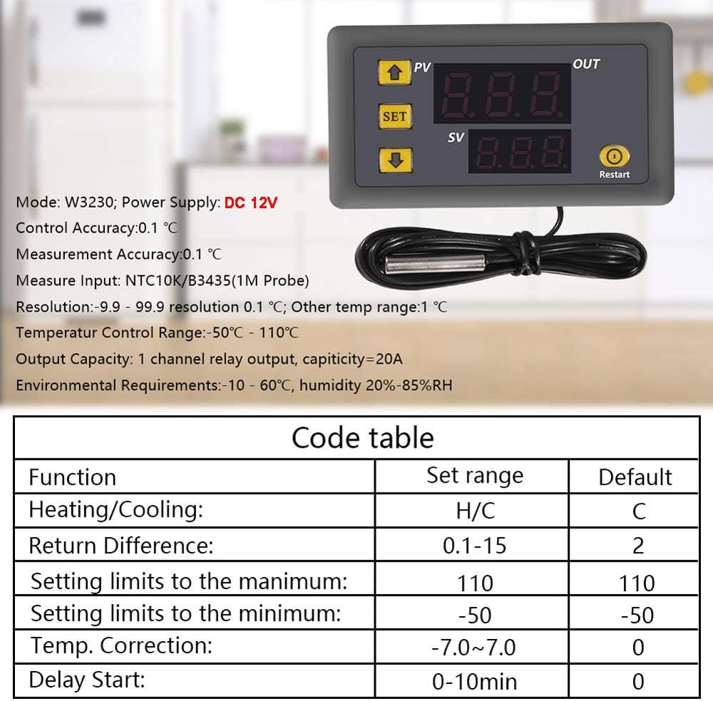
Image 3.1: W3230 specifications including control accuracy, measurement input, resolution, temperature control range, output capacity, and environmental requirements. Also includes a code table for various functions.
4. Setup and Installation
Proper circuit connection is crucial for the safe and correct operation of the W3230 temperature controller. Always ensure the power supply and load are connected according to the diagram.
4.1. Wiring Diagram
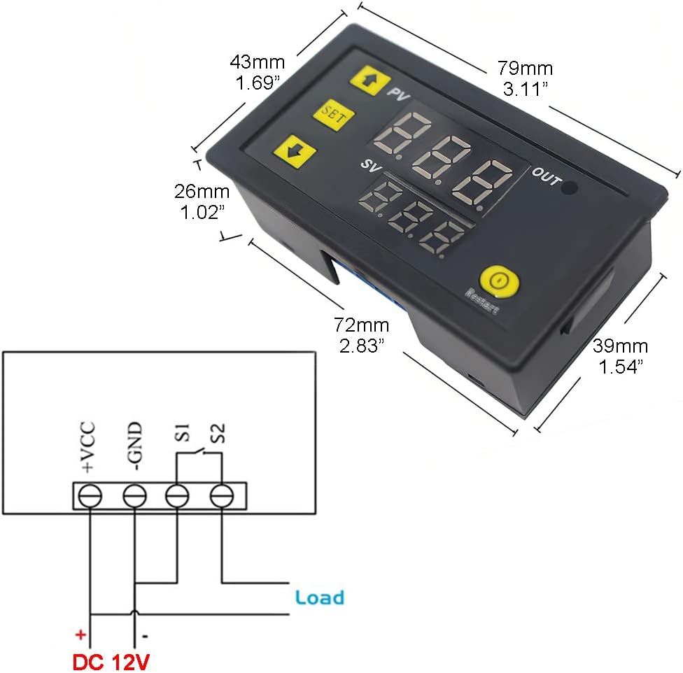
Image 4.1: Wiring diagram for the W3230. Connect DC 12V to +VCC and -GND terminals. The load is connected to S1 and S2 terminals, which are the relay output.
Connection Steps:
- Connect the DC 12V power supply to the +VCC and -GND terminals. Ensure correct polarity.
- Connect your load (e.g., heating element, cooling fan) to the S1 and S2 terminals. These are the relay output contacts.
- Ensure the NTC 10K sensor probe is securely connected to the designated sensor input.
Important: The working power supply voltage must be connected according to the standard voltage of the label (DC 12V). Otherwise, the module may be damaged.
5. Operation
The W3230 controller allows for easy setting of target temperatures and various operational parameters.
5.1. Setting Target Temperature (SV)
- Press the SET button briefly. The bottom digital tube (SV) will flash.
- Use the Up (▲) and Down (▼) buttons to adjust the desired target temperature.
- Press the SET button again to confirm and save the setting, or wait 3 seconds for it to save automatically.
5.2. Parameter Settings (P0-P8)
To access advanced settings, press and hold the SET button for 5 seconds until the display shows "P0". Use the Up/Down buttons to navigate through the parameters (P0-P8). Press SET to enter a parameter's setting, adjust with Up/Down, and press SET again to save.
| Code | Function | Set Range | Default |
|---|---|---|---|
| P0 | Heat/Cool Mode | H/C | C (Cooling) |
| P1 | Return Difference (Hysteresis) | 0.1°C - 30°C | 0.1°C |
| P2 | Set Upper Limit | -55°C - 120°C | 120°C |
| P3 | Set Lower Limit | -55°C - 120°C | -55°C |
| P4 | Calibration | -10°C - 10°C | 0°C |
| P5 | Delayed Start | 0 - 10 min | 0 min |
| P6 | Alarm Temperature | -55°C - 120°C | 120°C |
| P7 | Data Lock | ON/OFF | OFF |
| P8 | Factory Reset | ON/OFF | OFF |
Note: The last parameter setting is saved by default after shutdown. To restore factory settings, press and hold "SET" to power on.
6. Troubleshooting
6.1. Digital Tube Display Issues
- If the digital tube displays "----":
- Check if the temperature sensor is missing or damaged. Reconnect or replace the sensor if necessary.
- If the digital tube displays "HHH":
- Indicates high temperature protection in heat mode. The temperature exceeds the alarm temperature. The relay in protection mode is automatically disconnected. The temperature should drop below the alarm temperature to return to normal.
- If the digital tube displays "LLL":
- Indicates low temperature protection in cooling mode. The relay in protection mode is automatically disconnected. The temperature should rise above the alarm temperature to return to normal.
6.2. General Issues
- No Power: Check the DC 12V power supply connection and ensure it is providing the correct voltage.
- Incorrect Temperature Reading: Ensure the sensor probe is correctly placed and not damaged. Consider using the P4 Calibration function if a slight offset is observed.
- Relay Not Activating: Verify the P0 setting (Heat/Cool mode) and P1 (Hysteresis) are configured correctly for your application. Check the load connection.
7. Applications
The Greluma W3230 Digital Temperature Control is versatile and suitable for a wide range of applications requiring precise temperature management.

Image 7.1: Examples of W3230 applications. Suitable for environments such as greenhouses, warehouses, sanitizing equipment, and agricultural settings like farms.
- HVAC Systems: For controlling compressors in air conditioners and refrigeration units.
- Freezers & Refrigerators: Maintaining specific temperatures in cold storage.
- Fermentation Chambers: Ensuring stable temperatures for brewing or culturing.
- Water Coolers: Regulating water temperature.
- Aquariums: Maintaining optimal water temperature for aquatic life.
- Greenhouses: Controlling environmental temperature for plant growth.
- Industrial & Scientific Applications: General temperature control in various equipment.
8. Safety Information
- Always ensure the power supply matches the specified voltage (DC 12V). Incorrect voltage can damage the device.
- Do not expose the device to excessive moisture or extreme temperatures outside its operating range.
- Ensure all wiring connections are secure and insulated to prevent short circuits.
- Do not attempt to disassemble or modify the device beyond what is described in this manual.
- Keep out of reach of children.
9. Maintenance
- Keep the device clean and free from dust. Use a soft, dry cloth for cleaning.
- Regularly check wiring connections for looseness or corrosion.
- Ensure the sensor probe is clean and free from debris that could affect its accuracy.
10. Warranty and Support
For warranty information and technical support, please refer to the product packaging or contact Greluma customer service through the retailer where the product was purchased. Please have your product model number (W3230) and purchase details ready when contacting support.
For further assistance, you may also visit the official Greluma website or contact their authorized distributors.


