
1. Product Overview
The Generic MCU-6701 is a sensor module designed to measure the electrical activity of the skin (EDA), commonly known as galvanic skin response (GSR). EDA is a physiological characteristic reflecting continuous changes in the skin's electrical properties. This module is suitable for experimental research and applications requiring EDA monitoring, such as polygraphs, often used in conjunction with heart rate, respiratory rate, and blood pressure monitoring to assess the human autonomic nervous system.

Image: General view of the MCU-6701 GSR Skin Sensor Module.
2. Safety Information
Always handle electronic components with care. Ensure proper grounding to prevent electrostatic discharge (ESD) damage. Do not exceed the specified operating voltage. Disconnect power before making or changing connections. This module is intended for experimental and research purposes and should not be used for medical diagnosis or treatment without appropriate certification and professional supervision.
3. Package Contents
- 1 x CJMCU-6701 GSR Skin Sensor Module
4. Product Features
- Measures Electrical Activity of the Skin (EDA) / Galvanic Skin Response (GSR).
- Integrates MCP607 Micropower CMOS Op Amp (2.5V to 6.0V).
- Features MCP3201 12-Bit Analog-to-Digital Converter (ADC) with SPI Serial Interface (2.7V operation).
- Includes MCP1541 Precision Voltage Reference (2.5V and 4.096V).
- Provides both digital data via SPI and a buffered analog signal output for flexible processing.
5. Setup
The MCU-6701 module requires connection to a microcontroller (MCU) for power and data acquisition. Identify the pins on the module for proper connection:
- +5V: Power supply input (typically 5V, but compatible with 2.5V to 6.0V).
- GND: Ground connection.
- OUT: Buffered analog signal output.
- CS: Chip Select for SPI communication.
- MIS: Master In, Slave Out for SPI communication.
- SCK: Serial Clock for SPI communication.

Image: Top view of the MCU-6701 module, highlighting the pinout for power and data connections.
Connect the +5V and GND pins to your MCU's power supply. Connect the CS, MIS, and SCK pins to the corresponding SPI pins on your MCU. The OUT pin can be connected to an analog input pin on your MCU if you wish to read the raw analog signal directly, or to an external analog processing circuit.
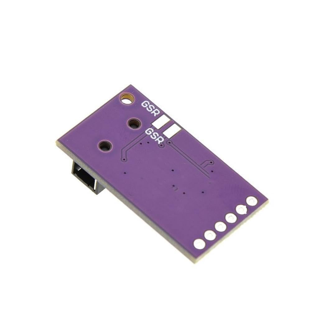
Image: Bottom view of the MCU-6701 module, indicating the GSR pads for electrode attachment.
Electrodes for GSR measurement should be connected to the 3.5mm audio jack on the module. Ensure the electrodes are clean and properly attached to the skin for accurate readings. Typically, two electrodes are placed on two different fingers of the non-dominant hand.
6. Operating Instructions
Once the module is powered and connected to your MCU, you can begin acquiring GSR data. The MCP3201 12-bit ADC converts the analog skin response into digital data, which can be read via the SPI interface.
SPI Data Acquisition:
- Initialize your MCU's SPI peripheral with appropriate clock speed and mode.
- To initiate a conversion and read data, pull the CS (Chip Select) pin LOW.
- Send the appropriate command byte(s) to the MCP3201 via the MOSI (Master Out, Slave In) line (if applicable, consult MCP3201 datasheet for specific commands, typically a start bit and channel selection for single-channel ADC).
- Read the 12-bit digital data from the MIS (Master In, Slave Out) line. The data will typically be transmitted as two 8-bit bytes.
- Pull the CS pin HIGH to end the communication.
- Process the 12-bit digital value. Higher values generally indicate lower skin resistance (higher conductivity).
Analog Output Reading:
If you are using the analog OUT pin, connect it to an analog input pin on your MCU. Use your MCU's internal ADC to read the voltage level. This voltage will correspond to the skin's conductivity. Calibration may be required to map the voltage range to meaningful GSR values.
For accurate measurements, ensure the subject is relaxed and still. Environmental factors such as temperature and humidity can influence GSR readings.
7. Maintenance
The MCU-6701 module is a low-maintenance device. Keep it clean and dry. Avoid exposing it to extreme temperatures, humidity, or corrosive environments. Periodically inspect connections for wear or damage. Store in an anti-static bag when not in use.
8. Troubleshooting
- No Readings/Erratic Data:
- Check all power and ground connections.
- Verify SPI connections (CS, MIS, SCK) and ensure correct wiring.
- Confirm that electrodes are properly attached to the skin and making good contact.
- Ensure the MCU's SPI configuration (mode, clock speed) matches the MCP3201 requirements.
- Inconsistent Readings:
- Check for environmental interference (e.g., electrical noise).
- Ensure the subject is calm and still during measurement.
- Verify electrode quality and placement.
- Consider adding filtering to the analog signal if noise is suspected.
- Module Not Powering On:
- Confirm power supply voltage is within the 2.5V to 6.0V range.
- Check for short circuits.
9. Specifications
| Parameter | Value |
|---|---|
| Model | MCU-6701 (CJMCU-6701) |
| Function | GSR / EDA Skin Sensor Module |
| Operating Voltage | 2.5V to 6.0V |
| ADC Resolution | 12-bit |
| Digital Interface | SPI Serial Interface |
| Analog Output | Buffered Analog Signal |
| Key Components | MCP607 Op Amp, MCP3201 ADC, MCP1541 Voltage Reference |
10. Warranty and Support
This product is provided by Generic. For specific warranty information or technical support, please refer to the retailer or manufacturer's official website where the product was purchased. Keep your purchase receipt for warranty claims.
