1. Introduction
This manual provides comprehensive instructions for the installation, operation, and maintenance of your ULNA CPE802T Wireless Bridge. This device is designed to extend network connectivity wirelessly over long distances, suitable for various outdoor environments.

Image 1.1: Three ULNA CPE802T Wireless Bridge units, showcasing the product design.
1.1 Package Contents
Please verify that all items listed below are included in your package:
- 3 x ULNA CPE802T Wireless Bridge Units
- 3 x 24V 1000Mbps PoE Adapters
- 3 x 3FT Test Network Cables
- 1 x User Manual
- Installed Accessories (Mounting hardware)
2. Product Overview
The ULNA CPE802T is a high-performance dual-band wireless bridge designed for stable and high-speed network extension. It supports both Point-to-Point (PTP) and Point-to-Multipoint (PTMP) configurations.

Image 2.1: Overview of ULNA CPE802T Wireless Bridge highlighting 5KM range, 1000Mbps, One Key Bridge, Guest Mode, and Dual Band features.
2.1 Key Features
- Long Distance Transmission: Stable transmission up to 5 KM (3.1 miles).
- Dual Band Gigabit Speeds: Supports 2.4G (300Mbps) and 5.8G (900Mbps) for a combined 1200Mbps.
- Outdoor Durability: IP65 waterproof, ±6KV lightning-resistant, dustproof, and operates from -20°C to 75°C.
- Flexible Network Modes: Supports DHCP Server, Guest Mode, and broadcasts up to 4 SSIDs simultaneously.
- Enhanced Security: Built-in WPA-PSK/WPA2-PSK/WPA/WPA2 protocols to protect network security.
- Pre-configured Setup: Plug and Play functionality with LED indicators for status monitoring.

Image 2.2: High-performance dual-band capabilities, illustrating speeds for 5.8GHz and 2.4GHz bands.
2.2 Device Interfaces and Indicators
Familiarize yourself with the ports and LED indicators on the CPE802T unit:

Image 2.3: Detailed view of the CPE802T unit's bottom panel, showing the A-B Switch, Power Indicator, LAN1, LAN2, WLAN Signal Light, 12V 1A DC port (not included), Digital Tube, and Reset Button.
- A-B Switch: Used to designate the unit as a Master (A) or Slave (B) bridge.
- PWR (Power Indicator): Illuminates when the device is powered on.
- LAN1/LAN2: Ethernet ports for network connectivity. LAN1 is typically the PoE input.
- WLAN Signal Light: Indicates wireless signal strength.
- Digital Tube: Displays status or configuration information.
- Reset Button: Used to restore factory default settings.
3. Setup and Installation
3.1 Pre-configured Setup (Plug and Play)
The ULNA CPE802T units are pre-configured for ease of use. Follow these simple steps for initial setup:
- Step 1: Plug them in. Connect the PoE adapter to the CPE unit and a power source.
- Step 2: Align them to face each other. Ensure a clear line of sight between the Master and Slave units.
- Step 3: Pair successfully and start running. The LED indicators will confirm successful pairing and operation.
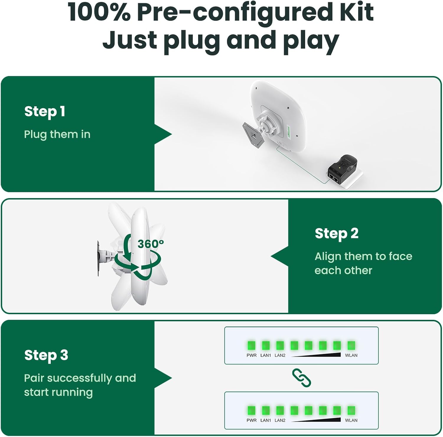
Image 3.1: Visual representation of the three-step "Plug and Play" setup process for the ULNA Wireless Bridge.
3.2 Physical Installation Guidelines
For optimal performance and durability, consider the following during physical installation:
- Line of Sight: Install units face-to-face within a Horizontal 60° / Vertical 30° angle with a clear, unobstructed line of sight. Obstacles like trees or buildings can significantly degrade performance.
- Mounting: Use the provided accessories to securely mount the units.
- Outdoor Environment: The CPE802T is designed to withstand harsh outdoor conditions.

Image 3.2: Illustration of the CPE802T's IP65 rating, indicating its resistance to sun, rain, thunder, frost, wind, and snow.
3.3 Connection Diagrams
The ULNA CPE802T can be deployed in various scenarios to extend network coverage:

Image 3.3: Two detailed diagrams showing point-to-multipoint configurations: one for extending network to multiple outbuildings with routers and devices, and another for extending surveillance camera monitoring range with a DVR and switch.
- Extend Network to Outbuildings: Connect a Master CPE to your main network (modem/router) and deploy Slave CPEs at remote locations (e.g., barn, shop, garage) to provide internet access.
- Extend Surveillance Camera Range: Use a Master CPE connected to your DVR/NVR and Slave CPEs near IP cameras to transmit video feeds wirelessly.
4. Operation
4.1 Network Modes
The CPE802T supports Point-to-Multipoint (PTMP) connections, allowing one Master unit to communicate with multiple Slave units.

Image 4.1: Conceptual diagram of a point-to-multipoint connection, showing a central Master CPE unit wirelessly connecting to two Slave CPE units at remote locations.
4.2 Guest Mode and Multiple SSIDs
The device supports Guest Mode and can broadcast up to four SSIDs simultaneously, allowing for segregated network access.

Image 4.2: Illustration of the CPE802T's ability to broadcast four SSIDs (two 5.8G and two 2.4G, including guest networks) for flexible network management.
4.3 Network Security
The ULNA CPE802T incorporates advanced security protocols to protect your network from unauthorized access and data leakage.

Image 4.3: Visual representation of the supported wireless security protocols: WPA-PSK, WPA2-PSK, WPA, and WPA2.
4.4 Web Interface Access
For advanced configuration and monitoring, the CPE802T can be accessed via a web-based graphical user interface (GUI). This allows for customization of IP settings, network modes, and other parameters.

Image 4.4: Screenshots of the CPE802T's web interface, demonstrating options for IP address configuration and client status monitoring.
5. Maintenance
To ensure the longevity and optimal performance of your ULNA CPE802T Wireless Bridge, consider the following maintenance guidelines:
- Regular Inspection: Periodically check the physical condition of the units and mounting hardware, especially after severe weather.
- Clear Line of Sight: Ensure that the line of sight between units remains unobstructed by new foliage growth or other obstacles.
- Firmware Updates: Check the manufacturer's website or contact support for any available firmware updates to improve performance and security.
- Cleaning: Gently clean the exterior of the units with a soft, damp cloth if dust or dirt accumulates. Do not use harsh chemicals.
6. Troubleshooting
If you encounter issues with your ULNA CPE802T Wireless Bridge, refer to the following common troubleshooting steps:
- No Power:
- Ensure the PoE adapter is correctly connected to the unit and a working power outlet.
- Check the power indicator LED on the unit.
- No Network Connection:
- Verify that the Ethernet cables are securely connected to the LAN ports on both the CPE unit and your network device (router, PC).
- Check the LAN indicator LEDs on the CPE unit.
- Poor Signal/Low Speed:
- Confirm that there is a clear, unobstructed line of sight between the Master and Slave units.
- Adjust the alignment of the units to ensure they are directly facing each other.
- Check the WLAN signal strength indicator LEDs. More illuminated LEDs indicate a stronger signal.
- Reduce the distance between units if possible, or eliminate any new obstructions.
- Cannot Access Web Interface:
- Ensure your computer is connected to the same network segment as the CPE unit.
- Verify the IP address of the CPE unit and your computer's network settings.
- Try resetting the unit to factory defaults using the reset button (note: this will erase all custom configurations).
7. Specifications
| Feature | Detail |
|---|---|
| Brand | ULNA |
| Model Number | CPE802T |
| Package Dimensions | 11.02 x 9.21 x 7.95 inches |
| Item Weight | 5.66 pounds |
| Special Feature | Access Point Mode, Guest Mode, LED Indicator, Weatherproof |
| Frequency Band Class | Dual-Band (2.4GHz, 5.8GHz) |
| Wireless Communication Standard | 802.11a, 802.11ac |
| Compatible Devices | Personal Computer, Router, Security Camera, Smartphone, Starlink |
| Recommended Uses | Business, Gaming, Home |
| Connectivity Technology | Ethernet, Wi-Fi |
| Color | White |
| Antenna Type | Internal |
| Manufacturer | ULNA |
| FCC ID | 2A6ZR-CPE609 |
8. Warranty and Support
For specific warranty information and technical support, please refer to the documentation included with your product or contact ULNA customer service directly. Contact details are typically found on the product packaging or the manufacturer's official website.
Note: The provided product data does not contain specific warranty terms or direct support contact information. Please consult the manufacturer's official channels for the most accurate and up-to-date details.


