
1. Introduction
This manual provides detailed instructions for the installation, operation, and maintenance of the BIGTREETECH EBB42 CAN Bus+ U2C V2.1 Hot End PCB Board Adapter Board. This product is designed to simplify wiring and enhance the functionality of 3D printer tool heads, particularly for Klipper-based systems.
2. Product Features
- Integrated MAX31865: Supports 2-wire or 4-wire PT100/PT1000 thermistor selection.
- Communication Options: Supports both CAN bus and USB communication for flexible connectivity.
- CAN Bus Termination: 120R terminal resistance for CAN can be selected via a jumper cap.
- Expansion Interfaces: Reserved CAN expansion interface and RGB interface for lighting needs.
- Simplified Wiring: Reduces wiring complexity for 36-step (42-step) motor extruder nozzle adapter boards.
- Firmware Update: BOOT and RESET buttons are reserved for DFU mode firmware updates via USB.
- Enhanced Security: USB power-on selection via jumper cap isolates DC-DC and USB 5V. Includes thermistor protection circuit and ESD protection chip for the USB port.
- High-Performance U2C: Facilitates CAN bus connection with long data transmission, strong anti-noise capability, real-time performance, and high reliability.
- Immersion Gold PCB Surface: Provides better solderability and improved stress control.
- Onboard ADXL345 Accelerometer: For vibration analysis and input shaping.
3. Product Overview
The BIGTREETECH EBB42 and U2C V2.1 boards work together to provide a robust and flexible solution for 3D printer tool heads.

Figure 3.1: Overview of the BIGTREETECH EBB42 and U2C V2.1 boards. The EBB42 (left) is a square board designed for the tool head, while the U2C V2.1 (right) is a rectangular board for connecting to the main control board, facilitating CAN bus communication.
3.1 EBB42 Extruder Breakout Board
The EBB42 is an Extruder Breakout Board designed for 36-step and 42-step motors. It integrates various functionalities directly onto the tool head.
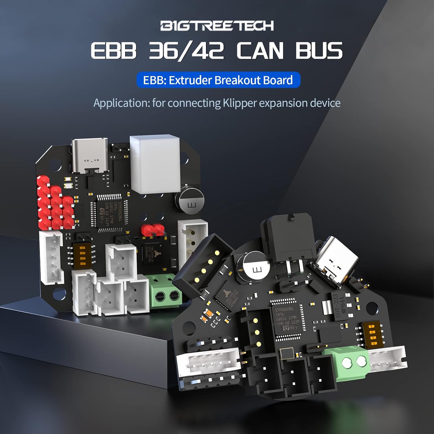
Figure 3.2: The BIGTREETECH EBB 36/42 CAN BUS board, an Extruder Breakout Board (EBB) for connecting Klipper expansion devices.
Key Components of EBB42:
- PT100/PT1000 Connector: Supports 2-wire or 4-wire thermistors.
- CAN Bus Interface: For robust communication.
- USB-C Port: For direct connection and firmware updates.
- 120R Jumper: Selectable CAN bus termination resistor.
- RGB Port: For connecting addressable LEDs.
- ADXL345 Accelerometer: Onboard for input shaping.
- Fan Connectors: FAN0, FAN1.
- Endstop/Probe Connectors: For limit switches and bed leveling probes.

Figure 3.3: Close-up of the EBB42 board highlighting the PT100/PT1000 support (2-wire or 4-wire via MAX31865), CAN bus connector, USB-C port, and the 120R jumper for CAN bus termination.

Figure 3.4: Detailed view of the EBB42 showing the reserved RGB port for illumination and the onboard ADXL345 accelerometer for motion sensing.
3.2 U2C V2.1 Adapter Board
The U2C V2.1 board acts as a USB to CAN bus adapter, enabling a Raspberry Pi or other host to communicate with CAN bus devices like the EBB42.

Figure 3.5: Top view of the BIGTREETECH U2C V2.1 Adapter Board, showing its various connectors and components.

Figure 3.6: Bottom view of the BIGTREETECH U2C V2.1 Adapter Board, displaying the CAN_H, CAN_L, and GND connections, along with jumper settings for 120R termination.
4. Setup and Installation
4.1 Physical Installation of EBB42
The EBB42 board is designed for mounting on the tool head. Ensure proper alignment and secure fastening.

Figure 4.1: Illustration of the EBB42 board's mounting points, suitable for 35mm, 36mm, or 42mm motors. Exercise caution during installation to prevent metal contact with the motherboard's pinheads, which could cause a short circuit.
Caution: To prevent short circuits, ensure that the pinheads of the motherboard do not come into contact with any metal surfaces during installation.
4.2 Wiring Connections
Carefully connect all necessary components to the EBB42 and U2C boards.
- Power Connection: Connect the appropriate power supply to the EBB42 board.
- Motor Connection: Connect your 36-step or 42-step extruder motor to the designated port on the EBB42.
- Thermistor Connection (PT100/PT1000):
- Identify if your thermistor is 2-wire or 4-wire.
- Set the jumper cap on the EBB42 to select between PT100 or PT1000, and 2-wire or 4-wire configuration as required by your thermistor. Refer to Figure 3.3 for jumper location.
- Fan Connections: Connect cooling fans to FAN0 and FAN1 ports.
- Endstop/Probe Connections: Connect limit switches or bed leveling probes to the respective ports.
- RGB LED Connection: If using, connect RGB LEDs to the reserved RGB port.
- CAN Bus Connection:
- Connect the CAN bus cable from the EBB42 to the U2C V2.1 board.
- Connect the U2C V2.1 board to your Raspberry Pi or host computer via USB.
- Ensure the 120R CAN bus termination resistor is correctly set on both the EBB42 (if it's the end of the bus) and the U2C V2.1 (if it's the end of the bus) using the jumper caps.
- USB Connection (Alternative/Firmware): The EBB42 can also be connected directly to a computer via its USB-C port for firmware updates or direct communication if CAN bus is not used.
4.3 Jumper Settings
Proper jumper configuration is crucial for correct operation and safety.
- PT100/PT1000 Selection: Adjust the jumper near the MAX31865 chip to match your thermistor type (PT100 or PT1000) and wiring (2-wire or 4-wire).
- CAN Bus 120R Termination: If the EBB42 or U2C V2.1 is the last device on the CAN bus line, enable the 120R termination resistor using the designated jumper. Refer to Figure 3.3 and Figure 3.6.
- USB Power Selection: The EBB42 allows selection of USB power-on via a jumper cap. This feature isolates the DC-DC converter and USB 5V of the main board, enhancing safety. Refer to Figure 4.2.

Figure 4.2: The EBB42 board illustrating the jumper for selecting USB power input, and highlighting the ESD protection for the USB port and surge protection features for enhanced safety.
5. Operation
5.1 Firmware Update
The EBB42 board's firmware can be updated via USB.
- Connect the EBB42 board to your computer using a USB-C cable.
- Press and hold the BOOT button, then press the RESET button. Release both buttons. This will put the board into DFU (Device Firmware Upgrade) mode.
- Use the appropriate firmware flashing tool (e.g., DFU-util) on your computer to upload the new firmware.
5.2 Klipper Configuration
For Klipper users, refer to the official Klipper documentation and BIGTREETECH resources for specific configuration files and instructions for the EBB42 and U2C boards. This typically involves configuring the CAN bus interface and defining the connected peripherals (motor, thermistor, fans, probe, ADXL345) in your printer.cfg file.
6. Maintenance
- Regular Inspection: Periodically check all wiring connections for looseness or damage.
- Cleaning: Keep the boards free from dust and debris. Use a soft brush or compressed air. Ensure power is disconnected before cleaning.
- Environmental Conditions: Operate the boards within recommended temperature and humidity ranges to ensure longevity.
7. Troubleshooting
- Board Not Detected:
- Check all power connections.
- Verify USB cable integrity if connecting directly via USB.
- For CAN bus, ensure correct wiring (CAN_H, CAN_L, GND) and proper 120R termination.
- Confirm that the U2C V2.1 is correctly connected to the host and its drivers are installed (if applicable).
- Thermistor Reading Errors:
- Check thermistor wiring for shorts or breaks.
- Ensure the PT100/PT1000 jumper setting matches your thermistor type and wiring configuration.
- Verify Klipper configuration for the thermistor type.
- Motor Not Responding:
- Check motor wiring connections.
- Verify power supply to the EBB42.
- Ensure Klipper configuration for the extruder motor is correct.
- Firmware Update Failure:
- Ensure the board is in DFU mode (BOOT and RESET sequence).
- Try a different USB cable or port.
- Verify the firmware file is correct and not corrupted.
8. Specifications
8.1 EBB42 Board Dimensions

Figure 8.1: Detailed dimensions of the EBB42 board, showing key measurements in millimeters for integration into 3D printer setups.
- Overall Dimensions: 40.00mm x 40.00mm (approximate, refer to diagram for precise measurements).
- Mounting Hole Spacing: Refer to Figure 8.1 for specific measurements.
8.2 General Specifications
- Microcontroller: STM32G0B1RET6
- Motor Driver: TMC2209 (onboard)
- Thermistor Support: PT100/PT1000 (2-wire/4-wire selectable) via MAX31865
- Communication: CAN Bus, USB-C
- Input Voltage: 12V-24V DC (typical for 3D printers)
- Onboard Accelerometer: ADXL345
- PCB Surface Treatment: Immersion Gold
9. Warranty and Support
For warranty information and technical support, please refer to the official BIQU website or contact your retailer. Keep your purchase receipt for warranty claims.