1. Introduction
This manual provides detailed instructions for the installation, operation, and maintenance of your Vikye H81 Mini ITX Motherboard. Please read this manual thoroughly before proceeding with installation to ensure proper setup and to maximize the performance and longevity of your system. This motherboard is designed for compact systems, supporting Intel 4th and 5th generation Core i3/i5/i7 processors with an LGA 1150 socket and DDR3 memory.
2. Product Overview and Features
The Vikye H81 Mini ITX Motherboard is built on the Intel H81 Express chipset, offering a stable and reliable platform for various computing needs, including desktop PCs and all-in-one systems. Its compact Micro ITX architecture makes it suitable for small form factor builds.
Key Features:
- LGA 1150 Socket: Supports Intel Core i3/i5/i7 4th and 5th generation CPUs (Haswell architecture).
- DDR3 Memory Support: Features dual 240-pin DDR3 S0 DRAM slots, supporting up to 16GB of memory at speeds of 1066/1333/1600 MHz.
- Integrated Gigabit Ethernet: Provides fast and stable network connectivity.
- Expansion Slots: Includes 1 M PCI Express slot and 1 M.2 NVMe slot for additional graphics cards, storage, or other expansion devices.
- High-Definition Audio: Equipped with a 6-channel HD audio codec, offering excellent sound quality and front audio interfaces.
- Rich I/O Interfaces: A comprehensive set of ports for connectivity, including USB 2.0, USB 3.0, VGA, HD Multimedia Interface compatible port, RJ45 network port, and audio jacks.

Figure 2.1: Top-down view of the Vikye H81 Mini ITX Motherboard, showing the CPU socket, RAM slots, and various connectors.

Figure 2.2: Angled view of the motherboard, highlighting its compact Mini ITX form factor and component layout.
3. Setup and Installation
Before beginning installation, ensure your workspace is clean and static-free. It is recommended to wear an anti-static wrist strap to prevent damage to components.
3.1 CPU Installation
- Locate the LGA 1150 CPU socket on the motherboard.
- Gently push down the load lever and pull it sideways to open the CPU socket cover.
- Carefully align the CPU with the socket, matching the golden triangle on the CPU with the triangle mark on the socket. Do not force the CPU into the socket.
- Once the CPU is seated, close the socket cover and secure it with the load lever.
- Apply a thin, even layer of thermal paste to the top of the CPU.
- Install the CPU cooler according to its manufacturer's instructions, ensuring it makes firm contact with the CPU.
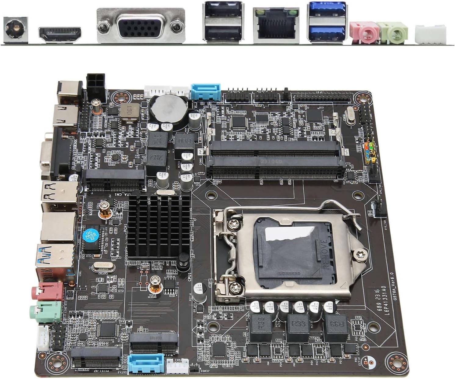
Figure 3.1: Close-up view of the LGA 1150 CPU socket, ready for processor installation.
3.2 Memory (RAM) Installation
- Locate the two DDR3 S0 DRAM slots.
- Open the clips at both ends of the memory slot.
- Align the notch on the DDR3 S0 DRAM module with the key in the memory slot.
- Insert the memory module firmly into the slot until the clips snap into place. Ensure both clips are fully closed.
- If installing two modules, use both slots for dual-channel operation.

Figure 3.2: The motherboard with its DDR3 S0 DRAM slots clearly visible for memory installation.
3.3 Storage Device Installation (M.2 NVMe / SATA)
- M.2 NVMe SSD: Locate the M.2 NVMe slot. Insert the M.2 SSD at an angle into the slot, then gently push it down and secure it with the provided screw.
- SATA Drives: Connect SATA data cables from your storage drives (HDD/SSD) to the SATA ports on the motherboard. Connect SATA power cables from your power supply to the drives.
3.4 Power Connections
- Connect the 12V DCIN power connector to the motherboard. This motherboard uses a DCIN (12V) power input.
- Ensure all other necessary power connections (e.g., to SATA drives) are made from your power supply.
3.5 Peripheral Connections
- Connect your display to the VGA or HD Multimedia Interface compatible port.
- Connect USB devices (keyboard, mouse) to the USB 2.0 or USB 3.0 ports.
- Connect an Ethernet cable to the RJ45 network port for wired internet access.
- Connect audio devices (speakers, headphones, microphone) to the respective audio jacks.
- Connect front panel headers (power button, reset button, USB, audio) from your PC case to the corresponding pins on the motherboard. Refer to your PC case manual for specific pin assignments.

Figure 3.3: Detailed view of the rear I/O panel, showing USB, VGA, HD Multimedia Interface, RJ45, and audio ports.
4. Operating Instructions
4.1 First Boot
- After all components are installed and connected, connect the power adapter to the DCIN port and a power outlet.
- Press the power button on your PC case.
- The system should power on, and you should see a display output.
- If no display appears, refer to the Troubleshooting section.
4.2 BIOS/UEFI Setup
The BIOS (Basic Input/Output System) or UEFI (Unified Extensible Firmware Interface) is firmware that initializes hardware during the booting process and provides runtime services for operating systems. To enter the BIOS/UEFI setup utility:
- During system startup, repeatedly press the designated key (commonly DEL, F2, F10, or F12). The exact key may vary; check the screen prompts during boot.
- Within the BIOS/UEFI, you can configure various system settings, including boot order, date/time, CPU settings, memory settings, and peripheral configurations.
- Save changes before exiting the BIOS/UEFI.
4.3 Operating System Installation
Once the hardware is set up and configured in BIOS/UEFI, you can proceed with installing your preferred operating system (e.g., Windows, Linux). Boot from your OS installation media (USB drive or DVD) and follow the on-screen instructions.
5. Maintenance
5.1 Cleaning
- Regularly clean dust from your computer case and motherboard components using compressed air. Ensure the system is powered off and unplugged before cleaning.
- Avoid using liquid cleaners directly on the motherboard.
5.2 BIOS/UEFI Updates
Periodically check the manufacturer's website for updated BIOS/UEFI firmware. Updates can improve system stability, compatibility, and performance. Follow the manufacturer's instructions carefully when performing firmware updates, as improper updates can damage the motherboard.
6. Troubleshooting
Common Issues and Solutions:
- No Power:
- Ensure the power adapter is securely connected to the motherboard's DCIN port and a working power outlet.
- Verify that the front panel power button cable is correctly connected to the motherboard.
- No Display:
- Check that the monitor is properly connected to the motherboard's video output (VGA or HD Multimedia Interface).
- Ensure the CPU and RAM are correctly installed. Try reseating the RAM modules.
- If using a dedicated graphics card in the PCI Express slot, ensure it is properly seated and powered, and connect your monitor to the graphics card's output.
- System Instability/Crashes:
- Check CPU and RAM temperatures. Ensure adequate cooling.
- Verify RAM modules are compatible and correctly installed.
- Ensure all drivers (chipset, graphics, etc.) are up to date.
- Operating System Not Booting:
- Check the boot order in BIOS/UEFI to ensure your primary storage drive is selected.
- Verify that the operating system is correctly installed on the storage drive.
- Check SATA or M.2 NVMe connections to the storage drive.
7. Specifications
| Feature | Detail |
|---|---|
| Model | H81 |
| CPU Support | Intel Core i3/i5/i7 4th/5th Generation (LGA 1150, Haswell architecture) |
| Chipset | Intel H81 Express |
| Memory | 2x 240-pin DDR3 S0 DRAM slots, up to 16GB, supports 1066/1333/1600MHz |
| Expansion Slots | 1x M PCI Express slot, 1x M.2 NVMe slot |
| Audio | Onboard 6-channel HD Audio Codec |
| Network | Integrated Gigabit Ethernet |
| Form Factor | Micro ITX |
| Battery | CR2032 (inbuilt) |
| Rear I/O Ports | |
| Power Input | 1x DCIN (12V) |
| USB Ports | 2x USB 2.0, 2x USB 3.0 |
| Video Outputs | 1x VGA, 1x HD Multimedia Interface compatible port |
| Network Port | 1x RJ45 |
| Audio Ports | 2x (Headphone Out, Microphone In) |
| Onboard Connectors | |
| Power Connector | 1x 4-pin ATX (12V/19V) |
| USB Headers | 2x USB headers (supporting 4x USB 3.0 ports) |
| Serial Ports | 2x Serial Connectors |
| Front Panel Headers | 1x F_PANEL, 1x F_Speaker |
| Fan Connectors | 2x Fan Connectors |
| LVDS Connectors | 1x JLVDS, 1x 30-pin LVDS CON |
| HD Multimedia Interface CON | 1x 16-pin HD Multimedia Interface Compatible CON |
| Inverter Connector | 1x 6-pin Inverter Connector |
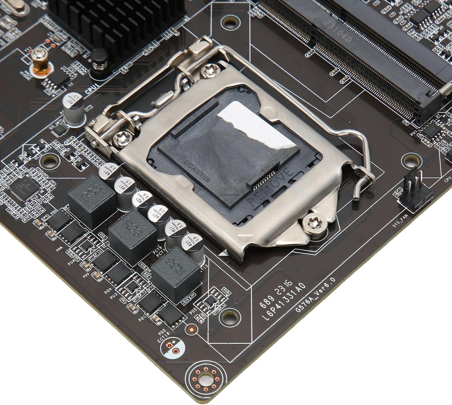
Figure 7.1: Detailed view of various I/O ports and onboard connectors.
8. Warranty and Support
For warranty information and technical support, please refer to the documentation provided with your purchase or contact Vikye customer service directly. Keep your proof of purchase for warranty claims.
Manufacturer: Vikye
Model Number: Vikyeysapi6xh2m
ASIN: B0CM7GJT4N


