1. Introduction and Safety Warnings
This manual provides essential information for the safe and effective use of the PerGar ETCR-1880 High Voltage Detector. Please read all instructions carefully before operation.
Important Safety Information
- The helmet alarm is not a voltage detector and must not be used as a primary voltage detection device.
- High-voltage operations are inherently dangerous. Operators must undergo strict training and obtain appropriate high-voltage operation certifications before using this instrument for on-site testing.
- This alarm is intended solely as a safety aid. Do not overestimate the safety assurance provided by wearing this alarm.
- When near grounded metal structures (e.g., transformers), the alarm's operating distance may not be reduced. Always exercise extreme caution.
2. Product Overview
The ETCR-1880 is a non-contact high voltage approach alarm designed to alert users to the presence of high voltage in the range of 1KV to 500KV. It features automatic detection and provides both audible and visual alarms.
Components

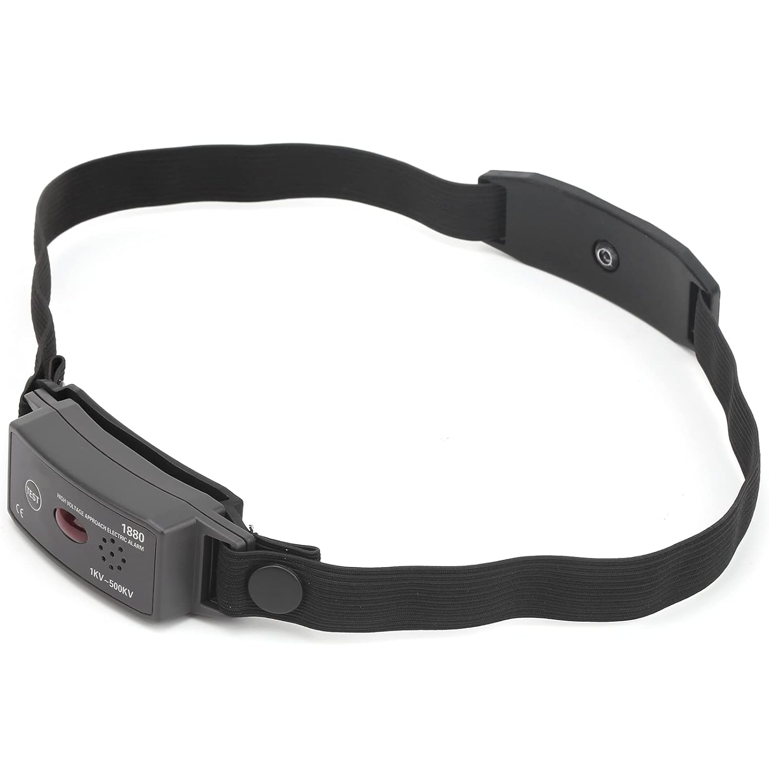
- Indicator Light: Provides visual alarm.
- Buzzer: Provides audible alarm.
- Test Button: Used to verify alarm functionality.
- Anti-Slip Rubber Pad: Helps secure the device.
- Adhesive: For attachment.
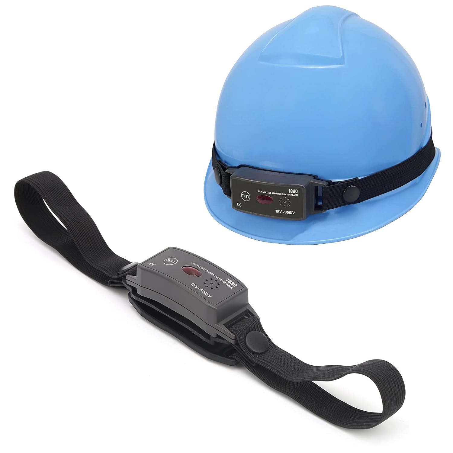
- Elastic Band: For wearing on a safety helmet.
3. Specifications
| Parameter | Value |
|---|---|
| Model | ETCR-1880 |
| Power Supply | 2 x CR1632 button batteries (not included) |
| Voltage Detection Range | 1KV-500KV |
| Deviation Error | ±10 cm (at 23℃, ±1℃, 80% basic conditions) |
| Operating Frequency | 50/60 Hz |
| Detection Mode | Automatic Trigger, Non-Contact |
| Continuous Operation Battery Life | Approx. 24 hours (sound and light alarm) |
| Standby Battery Life | Approx. 12 months |
| Alarm Mode | LED visibility under 8000LX visible light, Buzzer >60 dB (at 60 cm distance) |
| Protection Level | IP54 |
| Working Environment | -10℃ to 40℃; Humidity <80% |
| Storage Environment | -10℃ to 60℃; Humidity <70% |
| Manufacturer Model Number | PerGarvpsez2qd83 |
| ASIN | B0CLP9CR4N |
Voltage and Alarm Distance
| Voltage Level | Alarm Distance |
|---|---|
| 1KV | 0.1 m |
| 6.6KV | 0.6 m |
| 10KV | 0.8 m |
| 35KV | 1.4 m |
| 66KV | 1.8 m |
| 110KV | 2.2 m |
| 220KV | 3.0 m |
| 330KV | 3.6 m |
| 500KV | 4.2 m |
4. Setup
4.1 Battery Installation
The ETCR-1880 requires two CR1632 button batteries. To install or replace batteries:
- Locate the battery compartment on the device.
- Open the compartment cover.
- Insert two CR1632 batteries, observing correct polarity.
- Close the battery compartment cover securely.
4.2 Attaching to a Safety Helmet
For optimal safety and performance, the alarm should be worn on a safety helmet.
- Use the elastic band and adhesive pads to securely attach the ETCR-1880 to your safety helmet.
- Ensure the triangular shield on the device's appearance is visible and the alarm point is directed towards your fingertips. This orientation is crucial for proper detection.
5. Operating Instructions
The ETCR-1880 operates with an automatic trigger detection mode, simplifying its use and reducing the potential for human error.
5.1 Power On and Self-Test
Upon battery installation, the device automatically powers on. It is recommended to perform a self-test before each use:
- Press the Test Button on the device.
- Verify that the Indicator Light illuminates and the Buzzer emits an audible alarm. This confirms the device is functioning correctly.
5.2 High Voltage Detection
The ETCR-1880 uses non-contact induction technology to detect the presence of high voltage. When the device approaches a high-voltage source within its specified alarm distance, it will activate its alarm:
- The Indicator Light will flash.
- The Buzzer will emit an audible warning sound.
Refer to the 'Voltage and Alarm Distance' table in the Specifications section for approximate detection distances for various voltage levels.

6. Maintenance
6.1 Battery Replacement
Replace the CR1632 batteries when the alarm becomes weak or fails to activate during a self-test. Refer to Section 4.1 for battery installation instructions.
6.2 Cleaning
To clean the device, wipe it with a soft, damp cloth. Do not use abrasive cleaners or solvents. Ensure the device is dry before storage or next use.
6.3 Storage
Store the ETCR-1880 in a dry environment within the specified storage temperature range of -10℃ to 60℃ and humidity less than 70%. Remove batteries if storing for extended periods to prevent leakage.
7. Troubleshooting
- Device does not power on or alarm is weak: Check battery installation and replace with fresh CR1632 batteries if necessary.
- No alarm when near high voltage: Ensure the device is correctly positioned on the helmet as described in Section 4.2. Verify the device is functioning by pressing the Test Button. Confirm the voltage source is within the detection range (1KV-500KV).
- False alarms: Ensure the device is not near other strong electromagnetic fields or grounded metal structures that might interfere with its operation.
8. Additional Product Views