1. Introduction
The Micsig MDP3001 is a high-performance differential oscilloscope probe designed for safe and accurate measurement of high voltage signals. It features a 150MHz bandwidth, dual range selection, quick zero adjustment, and USB power supply, making it suitable for various power electronics and industrial applications. This manual provides essential information for the proper setup, operation, and maintenance of your MDP3001 probe.
2. Safety Information
Please read and understand all safety instructions before using the Micsig MDP3001 probe. Failure to follow these instructions may result in electric shock, injury, or damage to the equipment.
- High Voltage Warning: This probe is designed for high voltage measurements. Always exercise extreme caution when working with high voltages.
- Grounding: Ensure the oscilloscope and the device under test are properly grounded.
- Insulation: Do not touch the probe tips or any uninsulated parts when the probe is connected to a live circuit.
- Environmental Conditions: Use the probe only in dry conditions. Avoid using it in damp or wet environments.
- Damage Inspection: Before each use, inspect the probe, cables, and accessories for any signs of damage. Do not use if damaged.
- Qualified Personnel: Only qualified personnel should operate this equipment.
3. Product Overview
The Micsig MDP3001 is a high-voltage differential probe that allows an oscilloscope to safely measure floating voltages up to 3000Vpk. It converts high differential voltages to lower, single-ended voltages compatible with standard oscilloscope inputs.
3.1 Key Features
- Bandwidth: 150 MHz
- Differential Voltage Range: Dual range selection for various measurement needs.
- Input Impedance: High input impedance for minimal circuit loading.
- Power Supply: Convenient USB 5V power supply.
- Quick Zero Function: For accurate baseline adjustment.
- Output Interface: Standard BNC connector for oscilloscope compatibility.
3.2 Package Contents
The MDP3001 package typically includes the following items:
- Micsig MDP3001 High Voltage Differential Probe
- USB Power Cable
- Red and Black Test Leads
- Red and Black Alligator Clips
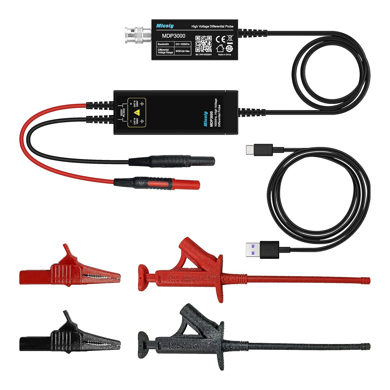
Figure 3.1: Micsig MDP3001 High Voltage Differential Probe with included accessories, including the probe unit, USB power cable, and test leads with alligator clips.

Figure 3.2: Detailed view of the MDP3001 probe module, highlighting the BNC output, USB power input, and input terminals for test leads, along with bandwidth and voltage range specifications.

Figure 3.3: The compact size of the MDP3001 probe, shown held in a hand for scale.
4. Setup
Follow these steps to set up your Micsig MDP3001 probe for measurement:
- Connect to Oscilloscope: Connect the BNC output of the MDP3001 probe to an input channel of your oscilloscope using a standard BNC cable.
- Power the Probe: Connect the USB power cable to the MDP3001 probe and to a 5V USB power source (e.g., oscilloscope USB port, computer USB port, or USB power adapter). The probe requires external power to operate.
- Attach Test Leads: Connect the red and black test leads to the input terminals of the MDP3001 probe. Ensure a secure connection.
- Attach Alligator Clips: If needed, attach the red and black alligator clips to the ends of the test leads for easier connection to the circuit under test.
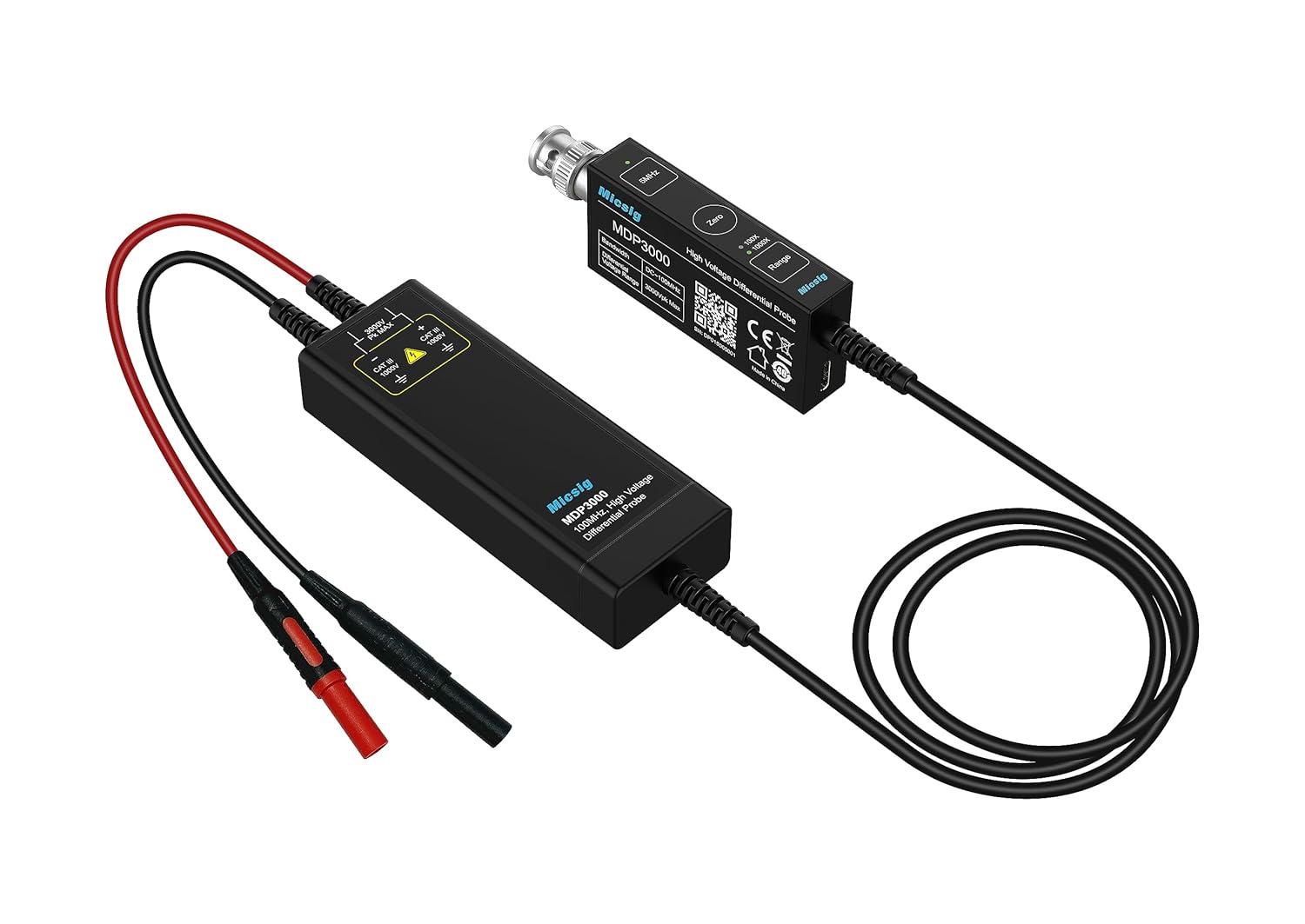
Figure 4.1: The MDP3001 probe connected to an oscilloscope, illustrating the BNC connection and the input leads ready for connection to a circuit.
5. Operating Instructions
Once the probe is set up, follow these steps for accurate measurements:
- Power On: Ensure the probe is powered via USB and the oscilloscope is turned on.
- Select Range: The MDP3001 features dual range selection. Choose the appropriate range based on the expected voltage of the signal you are measuring. Refer to the probe's label or specifications for range details.
- Quick Zero Adjustment: Before connecting to the circuit, short the red and black input leads together. Press the "Quick Zero" button on the probe (if available, or follow oscilloscope's zeroing procedure) to eliminate any offset voltage. This ensures accurate differential measurements.
- Connect to Circuit: Carefully connect the red and black test leads (or alligator clips) to the two points in the circuit where you wish to measure the differential voltage. Ensure secure and safe connections, especially with high voltages.
- Oscilloscope Settings: Adjust your oscilloscope's vertical scale (Volts/Div) and horizontal scale (Sec/Div) to properly display the waveform. Remember to account for the probe's attenuation ratio when interpreting the displayed voltage.

Figure 5.1: Example of a differential voltage waveform displayed on an oscilloscope screen using the MDP3001 probe.

Figure 5.2: Another example of a waveform captured by the probe and displayed on an oscilloscope, demonstrating signal integrity.
6. Maintenance
Proper maintenance ensures the longevity and accuracy of your MDP3001 probe.
- Cleaning: Use a soft, dry cloth to clean the probe and cables. Do not use abrasive cleaners or solvents. Ensure the probe is disconnected from all power sources before cleaning.
- Storage: Store the probe and its accessories in a clean, dry, and dust-free environment when not in use. Avoid extreme temperatures and humidity.
- Cable Care: Avoid sharp bends or kinks in the cables. Do not pull on the cables to disconnect them; always grasp the connector.
7. Troubleshooting
| Problem | Possible Cause | Solution |
|---|---|---|
| No signal on oscilloscope | Probe not powered; incorrect oscilloscope input selection; faulty cable connection; probe damaged. | Ensure USB power is connected and active. Verify oscilloscope input channel is selected. Check all BNC and test lead connections. Inspect probe for damage. |
| Incorrect voltage reading | Wrong attenuation setting on oscilloscope; incorrect probe range selected; offset not zeroed. | Adjust oscilloscope's vertical scale to match probe's attenuation. Select the appropriate range on the probe. Perform a Quick Zero adjustment. |
| Noisy or distorted waveform | Poor grounding; electromagnetic interference; damaged probe or cables. | Ensure proper grounding of all equipment. Minimize external interference. Inspect probe and cables for damage. |
8. Specifications
| Parameter | Value |
|---|---|
| Model | MDP3001 |
| Bandwidth | 150 MHz |
| Differential Voltage Range | Dual Range (e.g., ±300V, ±3000Vpk Max Note: Specific ranges should be confirmed from product labeling or official documentation. Max 3000Vpk inferred from product image.) |
| Attenuation Ratio | (Typically 100X/1000X for high voltage differential probes Note: Specific ratios should be confirmed from product labeling or official documentation.) |
| Input Impedance | (Typically 4MΩ || 5pF differential Note: Specific impedance should be confirmed from product labeling or official documentation.) |
| Power Supply | USB 5V |
| Output Interface | BNC |
| Product Dimensions | 9.84 x 4.33 x 6.3 inches |
| Item Weight | 3.31 Pounds |
Note: For the most precise and up-to-date specifications, please refer to the official Micsig product documentation or contact Micsig support.
9. Warranty and Support
Micsig products are designed for reliability and performance. For information regarding warranty coverage, technical support, or service, please refer to the warranty card included with your product or visit the official Micsig website. Contact details for customer support are typically available on the manufacturer's website.


