
1. Introduction
The JESSINIE XY-BLDC is a high-performance 3-phase DC brushless Hall motor controller module designed for various applications requiring precise motor speed and direction control. This module supports a wide voltage range of 12V to 30V and can handle up to 200W of power. It features overcurrent protection, forward/reverse control, and speed regulation via PWM or analog input.
This manual provides detailed instructions for the proper setup, operation, and maintenance of your XY-BLDC motor controller module.
2. Product Overview
The XY-BLDC module integrates DFN packaging technology for efficient power management. It is specifically designed for DC brushless Hall motors with an electrical angle of 120 degrees. Key features include:
- Wide operating voltage range: 12V-30V DC
- Maximum rated current: 7A (peak 10A)
- Maximum power output: 200W
- Integrated overcurrent protection
- Support for forward and reverse motor rotation
- Brake function capability
- Speed regulation via PWM (Pulse Width Modulation) or 0-5V analog input
- Onboard 5V power supply output (max 10mA)
- Speed pulse signal output (5V amplitude, 1 pulse per revolution)
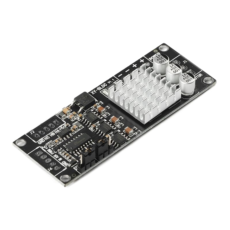
Figure 1: Angled view of the JESSINIE XY-BLDC Motor Controller Module.
3. Specifications
| Parameter | Value |
|---|---|
| Model | XY-BLDC |
| Working Voltage | 12V - 30V DC |
| Maximum Current | Rated 7A, Peak 10A |
| Maximum Power | 200W |
| Overcurrent Protection | Yes |
| Forward/Reverse Control | Yes |
| Brake Function | Yes |
| Speed Regulation | PWM or 0-5V Analog |
| Compatible Motors | DC Brushless Hall Motors (120° electrical angle) |
| Onboard 5V Output | Yes (max 10mA for external devices) |
| Speed Pulse Output | 5V amplitude, 1 pulse per revolution |
| Product Dimensions (L x W x H) | 80mm x 30mm x 10mm (3.15" x 1.18" x 0.39") |
| Product Weight | 15g |

Figure 2: Dimensions of the XY-BLDC Motor Controller Module.
4. Setup and Wiring
Before connecting the module, ensure all power sources are disconnected. Refer to the pinout diagram below for correct wiring.

Figure 3: XY-BLDC Module Pinout Diagram.
4.1 Power Input (J5)
- + (Positive): Connect to the positive terminal of your 12V-30V DC power supply.
- - (Negative): Connect to the negative (ground) terminal of your DC power supply.
Caution: Ensure correct polarity to prevent damage to the module.
4.2 Motor Output (J1)
- MA, MB, MC: Connect these terminals to the three phase wires of your brushless DC motor. The order may affect initial rotation direction; adjust if necessary.
4.3 Hall Sensor Input (J2)
Connect the Hall sensor wires from your brushless DC motor to these terminals.
- +5V: Hall sensor power supply (output from module).
- HA, HB, HC: Hall sensor signal inputs.
- GND: Hall sensor ground.
Note: This module is compatible only with DC brushless Hall motors with a 120-degree electrical angle.
4.4 Control Input (J6)
These pins are used for speed regulation and enable/disable functions.
- +5V: Onboard 5V power supply output (maximum 10mA for external devices).
- PWM: PWM signal input for speed control. Connect a PWM signal source (e.g., microcontroller) here.
- MAN (Analog): 0-5V analog voltage input for speed control. Connect an analog voltage source (e.g., potentiometer) here.
- GND: Ground for control signals.
- EN (Enable): Enable input. Typically, a high signal (e.g., 5V) enables the motor, and a low signal (0V or disconnected) disables it.
4.5 Direction (F/R) and Brake
The module includes dedicated pins or jumpers for forward/reverse control and brake functionality. Consult the specific markings on your board for these connections, which typically involve shorting pins or applying a control signal.
5. Operating Instructions
5.1 Speed Regulation
The XY-BLDC module supports two methods for speed control:
- PWM Control: Apply a Pulse Width Modulation signal to the PWM pin on J6. The motor speed will be proportional to the duty cycle of the PWM signal.
- Analog Control: Apply a 0-5V analog voltage to the MAN pin on J6. 0V typically corresponds to minimum speed (or stop), and 5V corresponds to maximum speed.
Note: Do not use both PWM and Analog control simultaneously. Select one method for speed regulation.
5.2 Forward/Reverse Control
The direction of motor rotation can be controlled via the F/R input. Refer to the board's specific markings for how to implement this (e.g., a switch or a digital signal).
5.3 Brake Function
The brake function allows for rapid stopping of the motor. Activate the brake via its dedicated input, as indicated on the module.
5.4 Speed Pulse Output
The module provides a speed pulse signal output with a 5V amplitude. Each pulse represents one full revolution of the motor. This can be used for external speed monitoring or feedback systems.
6. Safety Information
- Always disconnect power before making or changing any connections.
- Ensure proper ventilation for the module, especially during high-power operation, to prevent overheating.
- Do not exceed the maximum operating voltage (30V) or current (10A peak) to avoid damaging the module.
- Avoid short circuits on any terminals.
- Keep the module away from moisture, dust, and static electricity.
- This module is intended for use with DC brushless Hall motors only. Using it with other motor types may cause damage.
7. Maintenance
The XY-BLDC motor controller module requires minimal maintenance. Follow these guidelines to ensure its longevity:
- Keep the module clean and free from dust and debris. Use a soft, dry brush or compressed air for cleaning.
- Ensure the operating environment is within the recommended temperature and humidity ranges.
- Regularly inspect connections for any signs of wear or looseness.
8. Troubleshooting
If you encounter issues with your XY-BLDC module, consider the following common problems and solutions:
- Motor not spinning:
- Check power supply connections and ensure voltage is within 12V-30V.
- Verify motor phase (MA, MB, MC) and Hall sensor (HA, HB, HC) connections are correct and secure.
- Ensure the EN (Enable) pin is receiving a high signal.
- Confirm that a valid speed control signal (PWM or Analog) is being applied.
- Check if the motor is a compatible DC brushless Hall motor with a 120-degree electrical angle.
- Incorrect motor speed:
- If using PWM, verify the duty cycle and frequency of the PWM signal.
- If using analog, check the voltage level on the MAN pin (0-5V).
- Ensure no interference or noise is affecting the control signals.
- Motor runs in wrong direction:
- Adjust the F/R control input.
- Swap any two of the motor phase wires (MA, MB, MC) if F/R control is not available or not working as expected.
- Module overheating:
- Ensure adequate ventilation around the module.
- Verify that the motor load does not exceed the module's maximum current or power ratings.
- Check for any short circuits in the motor or wiring.
9. Warranty and Support
No specific warranty information is provided with this product. For technical support or further inquiries, please refer to the product's seller or manufacturer's official channels.