
Introduction
This manual provides detailed instructions for the installation, operation, and maintenance of your Docooler Wi-Fi Smart Programmable Thermostat. Please read this manual thoroughly before installation and use to ensure proper function and safety.
Package Contents
- 1 x Docooler Wi-Fi Smart Programmable Thermostat
- 2 x Mounting Screws
- 1 x English User Manual
Important Safety Information
- Always disconnect power at the circuit breaker before installing or servicing the thermostat.
- Installation should be performed by a qualified electrician.
- Ensure all wiring complies with local electrical codes.
- Do not operate the thermostat with wet hands.
- Keep the device away from water and high humidity environments.
Product Overview
Familiarize yourself with the thermostat's display and control buttons.

Image Description: A detailed view of the Docooler Wi-Fi Smart Programmable Thermostat's LCD screen, showing various icons and numerical displays. Numbered labels point to specific features: (1) Heating on indicator, (2) Periods display, (3) Monday to Sunday indicators, (4) External sensor indicator, (5) Down Button, (6) Up Button, (7) Clock icon, (8) Advanced options icon, (9) Mode button, (10) Power button, (11) Time display, (12) Set temperature, (13) Menu, (14) Room temperature, (15) Lock icon.
- Heating On: Indicates when the heating system is active.
- Periods: Displays the current programming period.
- Monday to Sunday: Day of the week indicator.
- External Sensor: Indicates if an external sensor is connected and active.
- Down Button: Decreases temperature or navigates menu options.
- Up Button: Increases temperature or navigates menu options.
- Clock: Displays the current time.
- Advanced Options: Accesses advanced settings.
- Mode: Switches between different operating modes (e.g., Manual, Program).
- Power: Turns the thermostat on or off.
- Time: Current time display.
- Set Temp: The desired temperature setting.
- Menu: Accesses the main menu for settings.
- Room Temp: Current room temperature.
- Lock: Indicates if the keypad is locked.
Setup
1. Installation
The thermostat is designed for installation in a standard 86x86mm square box or a European 60mm round box.
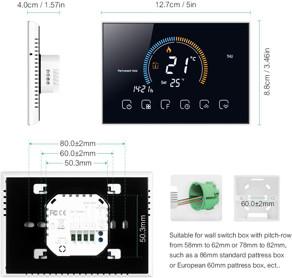
Image Description: Technical drawing showing the dimensions of the Docooler thermostat (12.7cm width, 8.8cm height, 4.0cm depth) and its back panel. The back panel includes a wiring terminal block and mounting hole measurements (80mm, 60mm, 50.3mm). It also illustrates compatible wall switch boxes: an 86mm standard box and a European 60mm round box.
Wiring Diagram for Water/Gas Boiler Systems
Ensure correct wiring connections for your water or gas boiler system. Refer to the diagram below.
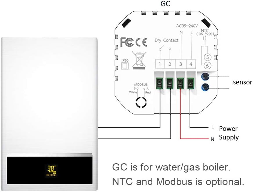
Image Description: A simplified wiring diagram illustrating the connection of the Docooler thermostat to a water/gas boiler system. The thermostat's back panel shows terminals for AC95-240V (L and N for power supply), Dry Contact (terminals 1 and 2 for boiler control), and optional NTC sensor (terminals 5 and 6) and Modbus (terminals 3 and 4). The diagram shows the L and N wires from the power supply connected to the thermostat, and the Dry Contact terminals connected to the boiler. An external NTC sensor is also shown connected.
Wiring Terminals:
- L & N: Power Supply (AC 95-240V, 50-60Hz)
- 1 & 2 (Dry Contact): Connect to your water/gas boiler control terminals.
- 3 & 4 (Modbus): Optional Modbus connection.
- 5 & 6 (NTC): Optional external NTC sensor connection.
General System Overview:

Image Description: A schematic diagram illustrating how the Docooler thermostat integrates into a typical home heating system. It shows a central heater connected to radiators, a shower bath, and a wash basin. The thermostat is positioned to control the heater, which then distributes hot water to the various outlets.
2. App Connection (Wi-Fi Models Only)
For Wi-Fi models, download the "My BecaSmart" application to control your thermostat remotely.
- Download App: Search for "My BecaSmart" in your smartphone's app store.
- Register/Login: Create an account or log in.
- Add Device: Follow the in-app instructions to add your thermostat. This typically involves putting the thermostat into pairing mode (refer to the thermostat's display for pairing indicators) and connecting to your home Wi-Fi network.
- Configuration: Once connected, you can configure settings, schedules, and control the thermostat from your phone.

Image Description: A series of smartphone screen captures showing the "My BecaSmart" application interface. One screen shows a "Connecting Now" progress bar at 9%, indicating device pairing. Another screen displays the main thermostat control interface with a large temperature dial (20.0°C) and icons for various functions. A third screen shows the "Impostazione programma" (Schedule Setting) interface, detailing daily temperature schedules for Saturday and Sunday with six time periods and corresponding temperature settings.
Operating Instructions
1. Basic Operation
- Power On/Off: Press the ⏻ (Power) button (labeled 10 in the diagram) to turn the thermostat on or off.
- Temperature Adjustment: Use the ▲ (Up) and ▼ (Down) buttons (labeled 6 and 5) to adjust the desired temperature.
- Mode Selection: Press the ⌛ (Mode) button (labeled 9) to switch between Manual mode and Program mode.
2. Programming (5+1+1 Six Periods)
The thermostat supports 5+1+1 day programming with six customizable periods per day (Monday-Friday, Saturday, Sunday).

Image Description: A composite image showing the thermostat display and a smartphone app. The thermostat display shows current temperature, day of the week, and weather icons, along with humidity (57%RH) and UV index. The smartphone app screen, labeled "Impostazione programma" (Schedule Setting), displays a detailed daily schedule for Saturday and Sunday, with six time periods and corresponding temperature settings (e.g., 06:00 20°C, 08:00 20°C, 11:30 20°C, 13:30 20°C, 17:00 20°C, 22:00 15°C).
- Enter Program Mode: Ensure the thermostat is in Program mode (indicated by a specific icon, usually a clock or calendar).
- Access Schedule Settings: Use the Menu button (labeled 13) or Advanced Options button (labeled 8) to navigate to the schedule settings.
- Set Periods: For each day group (Mon-Fri, Sat, Sun), set the start time and desired temperature for each of the six periods.
- Save Settings: Confirm and save your programming.
3. Smart Home Integration
The Docooler Wi-Fi thermostat is compatible with popular voice assistants for convenient control.
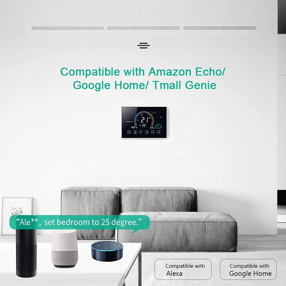
Image Description: An image depicting the Docooler thermostat mounted on a wall, with Amazon Echo and Google Home devices on a table below. Text indicates "Compatible with Amazon Echo/Google Home/Tmall Genie" and shows an example voice command: "Ale**, set bedroom to 25 degree." This illustrates the thermostat's integration with smart home ecosystems.
Supported Platforms:
- Amazon Alexa (Echo devices)
- Google Assistant (Google Home devices)
- Tmall Genie
To connect:
- Ensure your thermostat is connected to the "My BecaSmart" app and your home Wi-Fi.
- Open your Amazon Alexa or Google Home app.
- Search for the "My BecaSmart" skill/service and enable it.
- Link your "My BecaSmart" account with your voice assistant account.
- Discover devices. Your thermostat should now be controllable via voice commands.
Example Voice Command: "Alexa, set the living room thermostat to 22 degrees."
4. Lock Function
The lock function prevents unauthorized changes to the thermostat settings.
- To activate/deactivate the lock, press and hold the 🔒 (Lock) icon (labeled 15) for several seconds until the lock symbol appears or disappears on the display.
5. UV Index and Humidity Display
The thermostat provides real-time display of UV Index and ambient humidity levels for environmental awareness.

Image Description: The main display of the Docooler Wi-Fi Smart Programmable Thermostat. It shows a large current temperature of 21°C, a set temperature of 25°C, the current time (14:21), and the day (THU). Icons for heating, permanent hold, and various control functions are visible at the bottom. This image highlights the clear and comprehensive information presented on the screen.
Maintenance
Cleaning
- Wipe the thermostat's screen and casing with a soft, damp cloth.
- Do not use abrasive cleaners, solvents, or chemical sprays.
- Ensure no liquid enters the device.
Battery Replacement
This thermostat is typically hardwired and does not use user-replaceable batteries for primary operation. If your model includes a backup battery for settings retention, consult the specific instructions provided with your unit for replacement details.
Troubleshooting
Common Issues and Solutions
| Problem | Possible Cause | Solution |
|---|---|---|
| Thermostat not powering on | No power supply; incorrect wiring; circuit breaker tripped. | Check circuit breaker. Verify wiring connections (L & N). Ensure power is supplied to the unit. |
| Heating not turning on | Incorrect mode; set temperature too low; wiring issue to boiler. | Ensure thermostat is in heating mode. Increase set temperature above room temperature. Check boiler wiring (terminals 1 & 2). |
| Wi-Fi connection failure | Incorrect Wi-Fi password; weak signal; router issues; thermostat not in pairing mode. | Verify Wi-Fi password. Move thermostat closer to router. Restart router. Put thermostat into Wi-Fi pairing mode as per app instructions. |
| Inaccurate temperature reading | Thermostat located near heat source/draft; external sensor issue. | Relocate thermostat away from direct heat/cold sources. Check external sensor connection if used. |
| Keypad locked | Child lock or keypad lock activated. | Press and hold the lock icon (labeled 15) for several seconds to unlock. |
Technical Specifications
| Feature | Detail |
|---|---|
| Model | IBY5665215869606MF |
| Materials | PC + ABS |
| Voltage | AC 95-240V, 50-60Hz |
| Current Load | 5A |
| Power Consumption | <1.5W |
| Sensor | NTC3950, 10K |
| Accuracy | ±1°C or ±1°F |
| Set Temperature Range | 5-35°C |
| Display Temperature Range | 5-99°C |
| Ambient Temperature | 0-45°C |
| Ambient Humidity | 5-95% RH (non-condensing) |
| Storage Temperature | -5 ~ 45°C |
| Timing Error | <1% |
| Installation Box | 86x86mm square box or European 60mm round box |
| Wire Terminals | 2 x 1.5mm² or 1 x 2.5mm² wire |
| Protection Class | IP20 |
| Application | My BecaSmart |
| Item Dimensions | 12.7 x 4.0 x 8.8 cm |
| Item Weight | 231 g |
Warranty and Customer Support
For warranty information and technical support, please refer to the documentation provided with your purchase or contact Docooler customer service through their official website.