
1. Introduction
The SIGNALPLUS D3000 Discone Scanner Antenna is a high-performance, multi-band antenna designed for a wide range of radio communication equipment. It supports a broad frequency range from 25 MHz to 3000 MHz, making it suitable for receiving and transmitting signals across various bands including CB, UHF, VHF, HF, MW, SW, AIR, FM, FRS, and GMRS. Its robust construction features rust-free stainless steel elements, ensuring durability in diverse outdoor environments.
This manual provides comprehensive instructions for the assembly, installation, operation, and maintenance of your D3000 antenna to ensure optimal performance and longevity.
2. Setup
2.1. Unboxing and Components
Carefully unpack all components and verify that the following items are included:
- Discone Antenna elements (various lengths)
- Antenna base unit
- 10-meter RG58 coaxial cable with PL-259/UHF/SO-239 connector
- PL-259 female to BNC Male adapter
- PL-259 female to SMA Male adapter
- Mounting bracket and hardware (U-bolts, nuts, screws)
- Allen wrench for assembly

Figure 2.1: Included components: antenna elements, coaxial cable, adapters, and mounting hardware.
2.2. Antenna Assembly
Follow these steps to assemble your Discone antenna:
- Identify the main antenna base and the various radial elements. The D3000 features a unique design with three conical discs connected by a central shaft.
- Attach the longer radial elements to the upper section of the antenna base. These typically form the upper cone of the discone.
- Attach the shorter radial elements to the lower section of the antenna base. These form the lower cone, or ground plane, of the discone. Ensure all elements are securely fastened using the provided screws and Allen wrench.
- Connect the top loading coil if 25-50 MHz reception is desired. If not, this element can be omitted for a more compact and lightweight configuration.
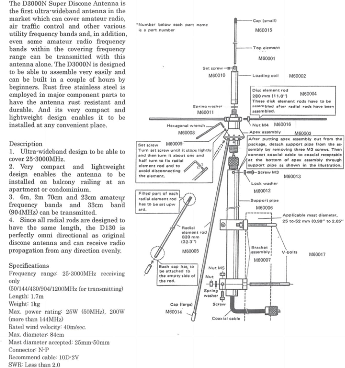
Figure 2.2: Detailed assembly diagram showing element placement and fastening points.
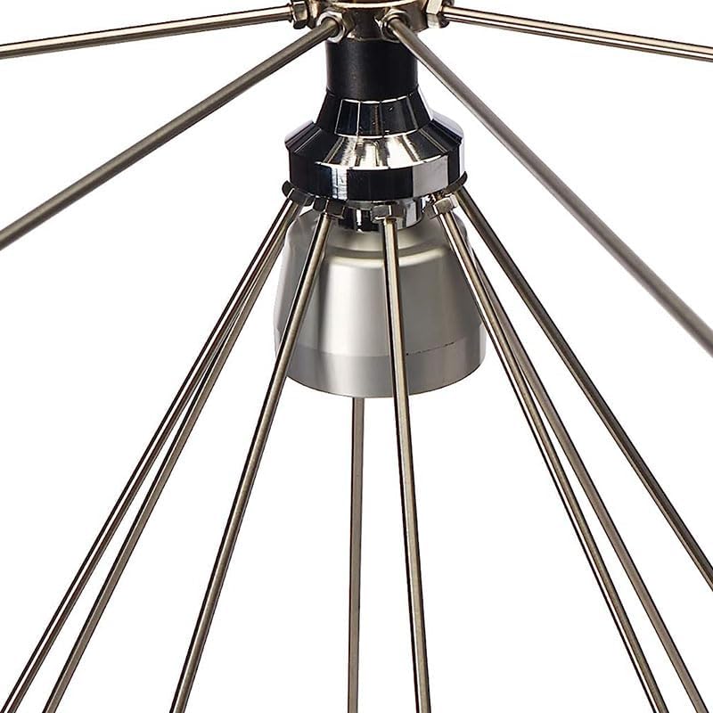
Figure 2.3: Close-up view of the antenna base with radial elements attached.
Video 2.1: This video demonstrates the assembly process of a similar multiband transmit and receive antenna, providing visual guidance for attaching radial elements and securing connections.
2.3. Installation
The D3000 antenna is designed for outdoor installation. Choose a location that provides a clear line of sight and is as high as possible for optimal performance. Suitable locations include rooftops, poles, or balcony railings.
- Secure the mounting bracket to your chosen surface using appropriate hardware. Ensure the bracket is firmly attached and level.
- Attach the assembled antenna to the mounting bracket. The antenna is adjustable, allowing for fine-tuning of its orientation.
- Connect the 10-meter RG58 coaxial cable to the SO-239 connector on the antenna base.
- Route the coaxial cable to your radio equipment, ensuring it is protected from physical damage and environmental elements. Avoid sharp bends in the cable.
- Use the provided adapters (PL-259 female to BNC Male or PL-259 female to SMA Male) if your radio requires a different connector type.

Figure 2.4: The D3000 Discone Antenna mounted on an outdoor pole, illustrating a typical installation scenario.
3. Operation
3.1. Connecting to Radio Equipment
Connect the coaxial cable from the D3000 antenna to the antenna input of your scanner, SDR radio, or ham radio. Use the appropriate adapter if necessary. Ensure all connections are tight and secure to prevent signal loss.
3.2. Supported Frequency Bands
The D3000 antenna is designed for optimal performance across a wide frequency spectrum:
- Receive Bands: 25-3000 MHz (MW, SW, HF, CB, AIR, UHF, VHF, FM, FRS, GMRS, 1090MHz, 978MHz, 27MHz)
- Transmit Bands: 144 MHz, 220 MHz, 440 MHz, 900 MHz, 1290 MHz
For specific frequency ranges, consult your radio equipment's manual for optimal settings and tuning procedures.
3.3. Optimizing Performance
To enhance reception and transmission, consider the following:
- Antenna Height: Install the antenna as high as possible to minimize obstructions and maximize signal reach.
- Cable Management: Use the shortest possible coaxial cable run and avoid kinks or sharp bends to reduce signal loss.
- Top Loading Coil: If you do not require reception in the 25-50 MHz range, the top loading coil can be removed to make the antenna more compact and lighter. This does not affect performance on higher frequencies.
Video 3.1: This product overview video provides a general look at the antenna and its features, which can aid in understanding its operation and capabilities.
4. Maintenance
The SIGNALPLUS D3000 antenna is constructed from rust-free stainless steel for long-term durability. Regular maintenance will ensure continued optimal performance.
- Cleaning: Periodically clean the antenna elements and base with a soft cloth and mild detergent to remove dirt, dust, and environmental buildup. Avoid abrasive cleaners.
- Inspection: Annually inspect all connections, mounting hardware, and coaxial cable for signs of wear, corrosion, or damage. Tighten any loose screws or connections.
- Environmental Protection: While designed for outdoor use, extreme weather conditions (heavy ice, strong winds) may require additional inspection or temporary removal if possible.
5. Troubleshooting
If you experience issues with your D3000 antenna, consider the following common troubleshooting steps:
- Poor Reception/Transmission:
- Verify all cable connections are secure and correctly attached.
- Check the coaxial cable for damage (kinks, cuts, severe bends).
- Ensure the antenna is mounted in a clear, unobstructed location.
- Confirm your radio equipment is correctly tuned to the desired frequency band.
- No Signal:
- Double-check that the antenna is properly assembled and all elements are in place.
- Inspect the adapters for correct type and secure connection.
- Test with a different coaxial cable if possible to rule out cable failure.
- Interference:
- Relocate the antenna away from potential sources of electrical interference (e.g., power lines, large electronic devices).
- Ensure proper grounding of your radio system.
6. Specifications
| Frequency Bands (Receive) | 25-3000 MHz |
| Frequency Bands (Transmit) | 144 MHz, 220 MHz, 440 MHz, 900 MHz, 1290 MHz |
| Gain | 2dBi - 3.5dBi |
| Max Power Rating (144 MHz up) | 200 watts |
| Max Power Rating (6m FM) | 20 watts |
| Max Power Rating (6m PEP) | 50 watts |
| Height | 1.7 meters (67 inches) |
| Product Dimensions | 33.07 x 33.07 x 66.93 inches (assembled) |
| Item Weight | 4.39 pounds |
| Connector Type | PL-259/UHF/SO-239 |
| Element Material | Rust-free stainless steel |
| Coaxial Cable | RG58 10 meters with SO-239 connector |
| Adapters Included | PL-259 female to BNC Male, PL-259 female to SMA Male |
| Impedance | 50 Ohms |

Figure 6.1: Dimensional drawing of the D3000 Discone Antenna, showing its height and width.
7. Warranty and Support
For warranty information, technical support, or any inquiries regarding your SIGNALPLUS D3000 Discone Scanner Antenna, please refer to the contact information provided with your purchase or visit the official SIGNALPLUS website. Keep your proof of purchase for warranty claims.