1. Introduction
This manual provides comprehensive instructions for the installation, operation, and maintenance of your ULNA AX3000 WiFi 6 Wireless Bridge CPE806S. This device is designed to extend network connectivity wirelessly over long distances, supporting both point-to-point (PTP) and point-to-multipoint (PTMP) configurations. Please read this manual thoroughly before using the product to ensure proper setup and optimal performance.
2. Package Contents
Verify that all items listed below are present in your package:
- 2 × ULNA CPE806S Wireless Bridge Units
- 2 × Bracket Mounts
- 2 × 24V 1000Mbps PoE Adapters
- 2 × 3FT Test Network Cables
- 4 × Large Metal Straps
- 2 × Small Metal Straps
- 1 × Mounting Kit (including screws and anchors)
- 1 × Quick Start Guide (this document)

Figure 2.1: Illustration of all components included in the ULNA CPE806S package.
3. Product Overview
The ULNA CPE806S is an outdoor WiFi 6 wireless bridge designed for robust and long-range network extension. Key features include:
- Next-Gen WiFi 6 Technology: Offers improved efficiency, capacity, and reduced latency for seamless long-range connections and real-time data transmission.
- 5KM Stable Wireless Transmission: Equipped with 5x 16dBi directional antennas, enabling up to 5KM point-to-point connectivity.
- 2.5Gbps & 1Gbps Dual Ethernet Ports: Features one 2.5Gbps high-speed LAN port and one 1Gbps LAN port for versatile connectivity.
- Dual Band WiFi Access: Each unit supports 2.4GHz and 5.8GHz WiFi dual-band access for local wireless connections at both ends.
- Two Power Options: Supports 24V passive POE and 12V/1A DC solar panel input for flexible outdoor power solutions. Note: Not compatible with 48V POE switches or 48V adapters.
- Outdoor Durability: Built with IP65-rated waterproof housing for harsh outdoor environments.

Figure 3.1: The ULNA AX3000 WiFi 6 Wireless Bridge CPE806S units.
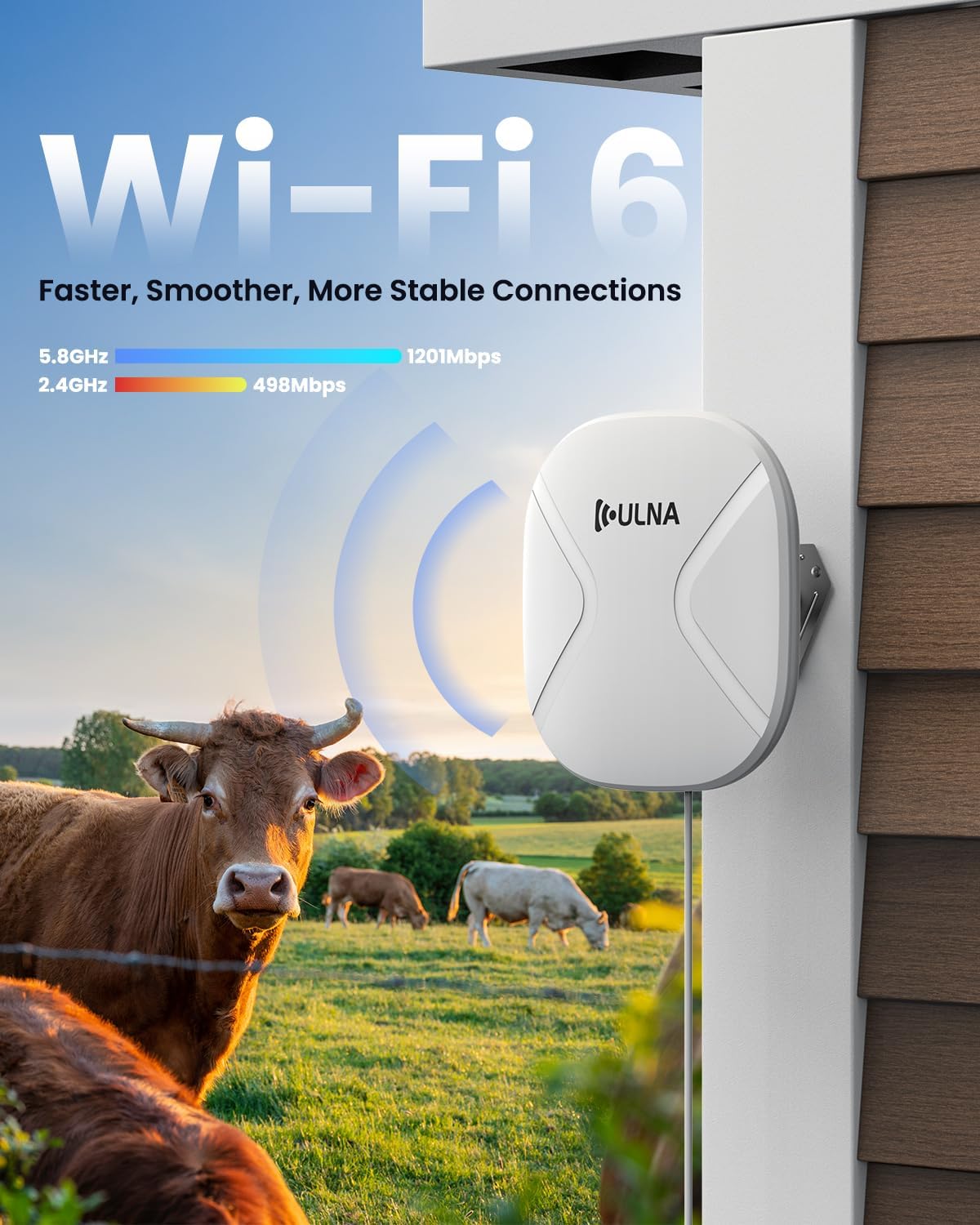
Figure 3.2: The device utilizes WiFi 6 technology for faster, smoother, and more stable connections across 2.4GHz and 5.8GHz bands.
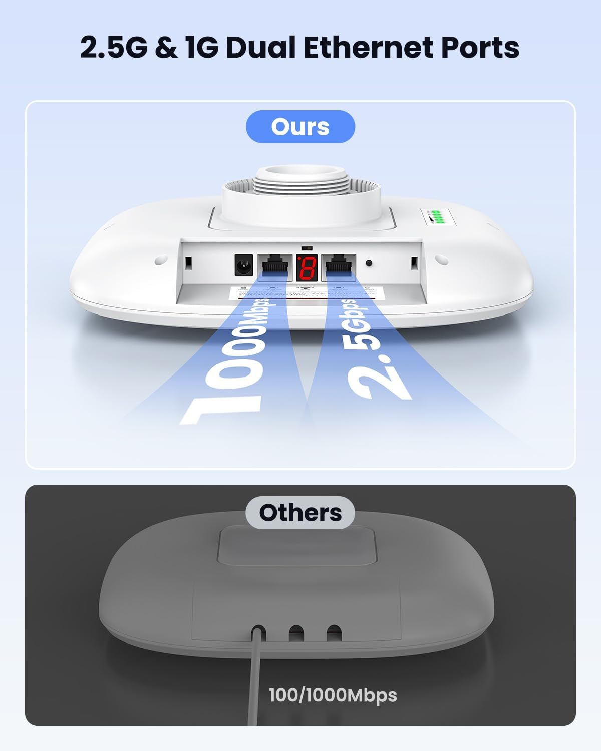
Figure 3.3: The CPE806S features 2.5Gbps and 1Gbps dual Ethernet ports for flexible networking.

Figure 3.4: The CPE806S supports two power options: 24V Passive PoE and 12V DC input, suitable for various outdoor installations.
4. Setup Instructions
The ULNA CPE806S is designed for plug-and-play setup. The units are pre-configured from the factory for instant pairing. Follow these steps for initial setup and various network configurations.
4.1. Initial Pairing and Channel Selection
- Power the Bridges: Connect the provided 24V PoE adapters to a power outlet. Then, plug the PoE port of each adapter into the corresponding PoE port on each CPE806S unit. The units will power on.
- Set Master and Slave: Designate one unit as the Master Bridge and the other as the Slave Bridge. Use a small tool to short press the 'Reset' button on the Master unit until its display shows 'A'. For the Slave unit, short press the 'Reset' button until its display shows 'B'.
- Select Channel: Short press the 'Reset' button on both units to select a channel (e.g., '6'). Ensure both Master and Slave units are set to the same channel.
- Verify Pairing: Wait for the SIG1-SIG4 lights on both units to light up. This indicates successful pairing.
Video 4.1: A step-by-step guide on how to set up your ULNA CPE806S Wireless Bridge, including powering, setting master/slave, and channel selection.
4.2. Network Extension (Wired/Wireless)
To extend your network to a remote location:
- Connect Internet Source to Master Bridge: Connect your main router's LAN port to the LAN port of the Master Bridge using an Ethernet cable.
- Connect Slave Bridge to Remote Device/Router:
- For Wired Internet Access: Connect the LAN port of the Slave Bridge to your computer's Ethernet port. Your computer will then receive a wired internet connection.
- For Wireless Internet Access: Connect the LAN port of the Slave Bridge to the WAN port of a secondary router. This secondary router will then broadcast WiFi in the remote location, allowing devices to connect wirelessly.

Figure 4.2: Example of extending network across properties, connecting a main router to the Master Bridge and a secondary router to the Slave Bridge for remote WiFi access.

Figure 4.3: The CPE806S allows dual-band WiFi access at both the transmitting and receiving ends, enabling direct connection of devices like laptops or IP cameras.
4.3. IP Camera Setup
For long-distance IP camera deployment:
- Connect NVR to Master Bridge: Connect your Network Video Recorder (NVR) to the LAN port of the Master Bridge.
- Power and Connect IP Camera to Slave Bridge: Power on your IP camera using its dedicated power adapter. Then, connect the IP camera's Ethernet port to the LAN port of the Slave Bridge.
- Configure NVR and Camera: Ensure the NVR and IP camera are configured to the same network segment (e.g., same IP address range). The live camera feed should then appear on your monitor connected to the NVR.

Figure 4.4: Setup for long-distance IP camera deployment, connecting an NVR to the Master Bridge and an IP camera to the Slave Bridge.
5. Operating Modes
The ULNA CPE806S supports two primary operating modes:
- Point-to-Point (PTP): This mode establishes a direct wireless link between two CPE806S units, extending network connectivity from one location to another. This is ideal for connecting two buildings or structures.
- Point-to-Multipoint (PTMP): In this mode, one Master Bridge can connect to multiple Slave Bridges, creating a network that extends to several remote locations. The Slave Bridges should be within a 60-degree angle from the Master Bridge for optimal performance. This is suitable for covering multiple outbuildings or areas from a central point.
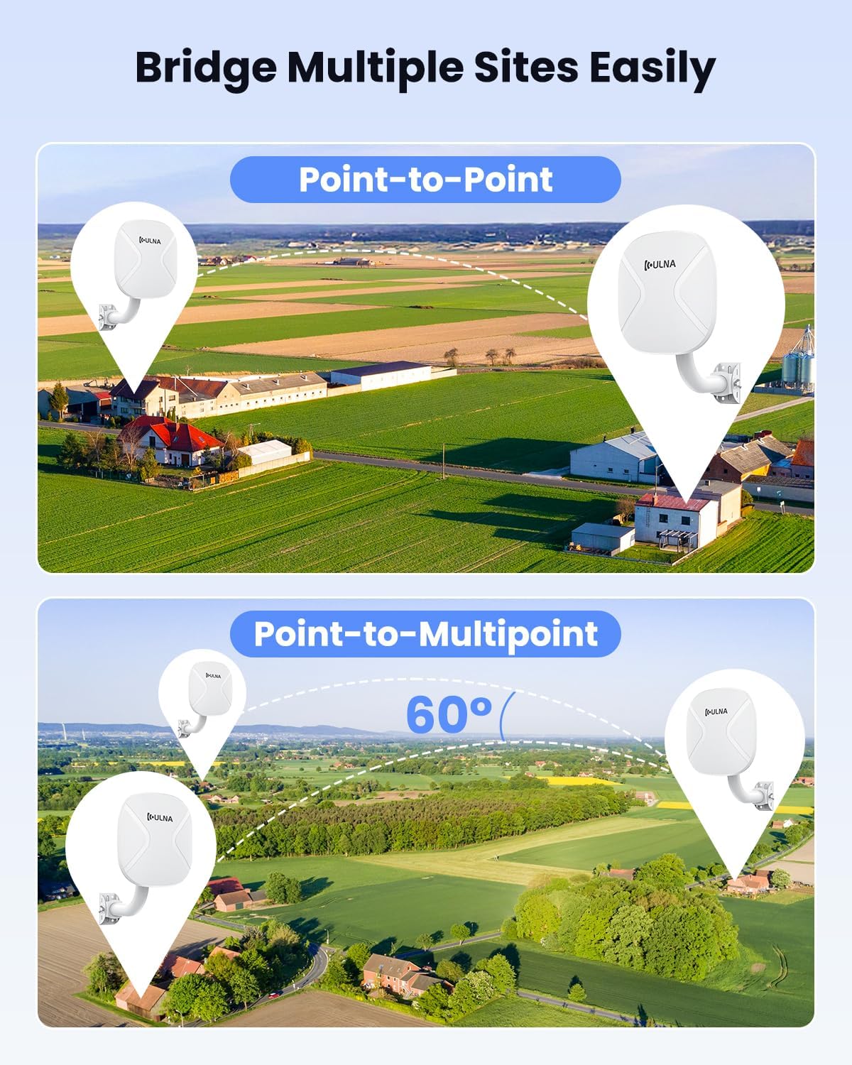
Figure 5.1: Visual representation of Point-to-Point and Point-to-Multipoint configurations for the ULNA Wireless Bridge.

Figure 5.2: A detailed example of a Point-to-Multipoint setup, connecting multiple remote devices via Slave Bridges to a central Master Bridge.
6. Installation Guidelines
Proper installation is crucial for optimal performance and durability of your outdoor wireless bridge.
- Line of Sight: For best results, ensure a clear line of sight between the Master and Slave Bridges. Obstructions like trees, buildings, or hills can significantly reduce signal strength and range.
- Mounting: Use the provided mounting brackets and metal straps for secure installation on rooftops or poles. The brackets allow for 150-degree adjustability to fine-tune alignment.
- Environmental Considerations: The CPE806S is designed to operate in temperatures ranging from -20°C (-4°F) to 75°C (167°F). Its IP65 rating ensures protection against dust and water jets.
- Alignment: Carefully align the units towards each other. The signal indicator lights on the units will help in achieving optimal alignment.

Figure 6.1: The CPE806S is suitable for outdoor use, featuring an adjustable mounting bracket and robust design for various weather conditions.
7. Specifications
Detailed technical specifications for the ULNA CPE806S Wireless Bridge:
| Feature | Specification |
|---|---|
| Model Name | CPE806S |
| Wireless Communication Standard | 802.11ac, 802.11ax (WiFi 6), 802.11b, 802.11g, 802.11n |
| Frequency Band Class | Dual-Band (2.4GHz & 5.8GHz) |
| Connectivity Technology | Ethernet, Wi-Fi |
| Ethernet Ports | 1x 2.5Gbps LAN, 1x 1Gbps LAN |
| Power Options | 24V Passive POE, 12V/1A DC Solar Panel Input |
| Outdoor Rating | IP65 Weatherproof Housing |
| Operating Temperature | -20°C to 75°C (-4°F to 167°F) |
| Item Weight | 6.6 pounds (per unit) |
| Package Dimensions | 12.6 x 10.24 x 10.08 inches |
8. Troubleshooting
If you encounter issues with your ULNA CPE806S, refer to the following common troubleshooting steps:
- No Power: Ensure the 24V PoE adapter is correctly plugged into a working power outlet and securely connected to the CPE806S unit. Verify the power indicator light is on.
- No Connection/Poor Signal:
- Check for clear line of sight between the Master and Slave Bridges. Remove any obstructions.
- Re-align the units to ensure they are pointing directly at each other. Observe the SIG indicator lights for optimal signal strength.
- Verify that both units are set to the same channel (A/B and channel number).
- Ensure the distance between units does not exceed the recommended maximum range for your environment.
- No Internet Access:
- Confirm that the internet source (modem/router) connected to the Master Bridge is active and providing internet.
- Check all Ethernet cable connections for security and integrity.
- If using a secondary router at the slave end, ensure it is correctly configured (e.g., WAN port connected to the Slave Bridge, proper DHCP settings).
- Slow Speeds:
- Optimize alignment for maximum signal strength (all SIG lights illuminated).
- Minimize interference from other wireless devices or networks by trying different channels.
- Ensure connected devices (computers, cameras) have gigabit Ethernet ports to utilize the full speed of the bridge.
9. Safety Information
Please observe the following safety precautions:
- Do not attempt to disassemble or modify the device. This may void the warranty and pose safety risks.
- Use only the provided power adapters. Using incompatible adapters may damage the device.
- Ensure proper grounding during installation to prevent electrical hazards.
- Avoid installing the device near sources of strong electromagnetic interference.
- When mounting, ensure the structure is stable and can support the weight of the device, especially in windy conditions.
10. Warranty and Support
ULNA products are covered by a standard manufacturer's warranty. For specific warranty terms, return policies, or technical support, please refer to the documentation included with your purchase or visit the official ULNA support website. Keep your purchase receipt for warranty claims.


