
EPEVER XTRA 1210N (10A, 12/24V, max PV 100V)
EPEVER MPPT XTRA-N XTRA1210N Solar Charge Controller User Manual
Model: XTRA 1210N (10A, 12/24V, max PV 100V)
1. Introduction
The EPEVER MPPT XTRA-N series solar charge controller is an advanced Maximum Power Point Tracking (MPPT) device designed for off-grid solar systems. It efficiently manages power flow from solar panels to batteries, ensuring optimal charging and extending battery life. This manual provides detailed instructions for the safe and effective operation of your XTRA 1210N charge controller.

Figure 1: EPEVER MPPT XTRA-N XTRA1210N Solar Charge Controller. This image shows the front view of the white and blue solar charge controller with its display and control buttons, indicating its 10A and 100V ratings.
2. Safety Information
Please read all instructions carefully before installation and operation. Failure to follow these instructions may result in damage to the unit, personal injury, or property damage.
- Ensure all connections are correct and secure before applying power.
- Do not exceed the maximum PV open circuit voltage (Voc) of 100V for the XTRA1210N model. Exceeding this limit can damage the controller.
- Connect the battery first, then the solar panel, and finally the load. Disconnect in the reverse order.
- Install the controller in a well-ventilated area, away from flammable materials and direct sunlight.
- This device is designed for indoor use only. Protect it from moisture and dust.
- Only qualified personnel should perform installation and maintenance.
3. Product Overview
The XTRA-N series features an improved design and performance over its predecessor, the Tracer AN series. Key features include advanced MPPT technology for precise tracking of multiple Maximum Power Points (MPP) of the solar module, potentially yielding 20-30% more power. Lithium battery parameters can be adjusted via the LCD display.
3.1 Components and Ports

Figure 2: Bottom view of the EPEVER MPPT XTRA-N charge controller showing various connection ports. Labels include Remote temperature sensor port, Mounting hole (size 5mm), Grounding Terminal, PV terminals, BATT1 terminals, BATT2 terminals, RS485 Communication port, AES (signal) output port, and LCD (Refer to chapter 3).
- LCD Display: Shows system status, parameters, and error codes.
- Control Buttons: For navigation and setting parameters.
- PV Terminals: Connect to solar panel array.
- Battery Terminals (BATT1, BATT2): Connect to battery bank.
- Load Terminals: Connect to DC loads.
- Remote Temperature Sensor Port: For external temperature compensation.
- RS485 Communication Port: For PC communication or external display.
- AES (Signal) Output Port: For specific applications.
- Grounding Terminal: For system grounding.
3.2 Supported Battery Types
The controller supports various battery types, including Lead-Acid (AGM, GEL, Flooded, USER defined) and Lithium batteries (LiFePO4, Li(NiCoMn)O2). Lithium battery parameters can be customized via the LCD display.

Figure 3: Image illustrating the supported battery types: Lead-Acid (Gel, AGM, Flooded, User) and Lithium (LiFePO4, Li(NiCoMn)O2).
4. Setup and Installation
Proper installation is crucial for the performance and longevity of your solar charge controller. Follow these steps carefully.
4.1 Mounting the Controller
- Choose a mounting location that is dry, well-ventilated, and protected from direct sunlight and moisture.
- Ensure there is sufficient space around the controller for heat dissipation.
- Mount the controller vertically on a non-flammable surface using appropriate screws.
4.2 Connection Sequence
Follow the connection sequence below to prevent damage to the controller or other components.

Figure 4: Diagram illustrating the recommended connection sequence for the solar charge controller. Step 1: Connect solar modules to form a 12V(2s) array. Step 2: Set up a 12V battery bank (battery not included). Step 3: Connect the charge controller to the battery bank. Step 4: Plug the solar module output into the PV input of the controller.
- Step 1: Connect the Battery. Connect the battery to the controller's battery terminals (BATT1 or BATT2). Ensure correct polarity (+ to + and - to -). The controller will power on.
- Step 2: Connect the Solar Panel. Connect the solar panel array to the controller's PV terminals. Ensure correct polarity. The controller will begin charging.
- Step 3: Connect the DC Load (Optional). Connect your DC loads to the controller's load terminals. Ensure correct polarity.
Disconnection Sequence: Disconnect the load first, then the solar panel, and finally the battery.
4.3 Accessory Connections
The controller supports various accessories for enhanced monitoring and control (accessories not included).
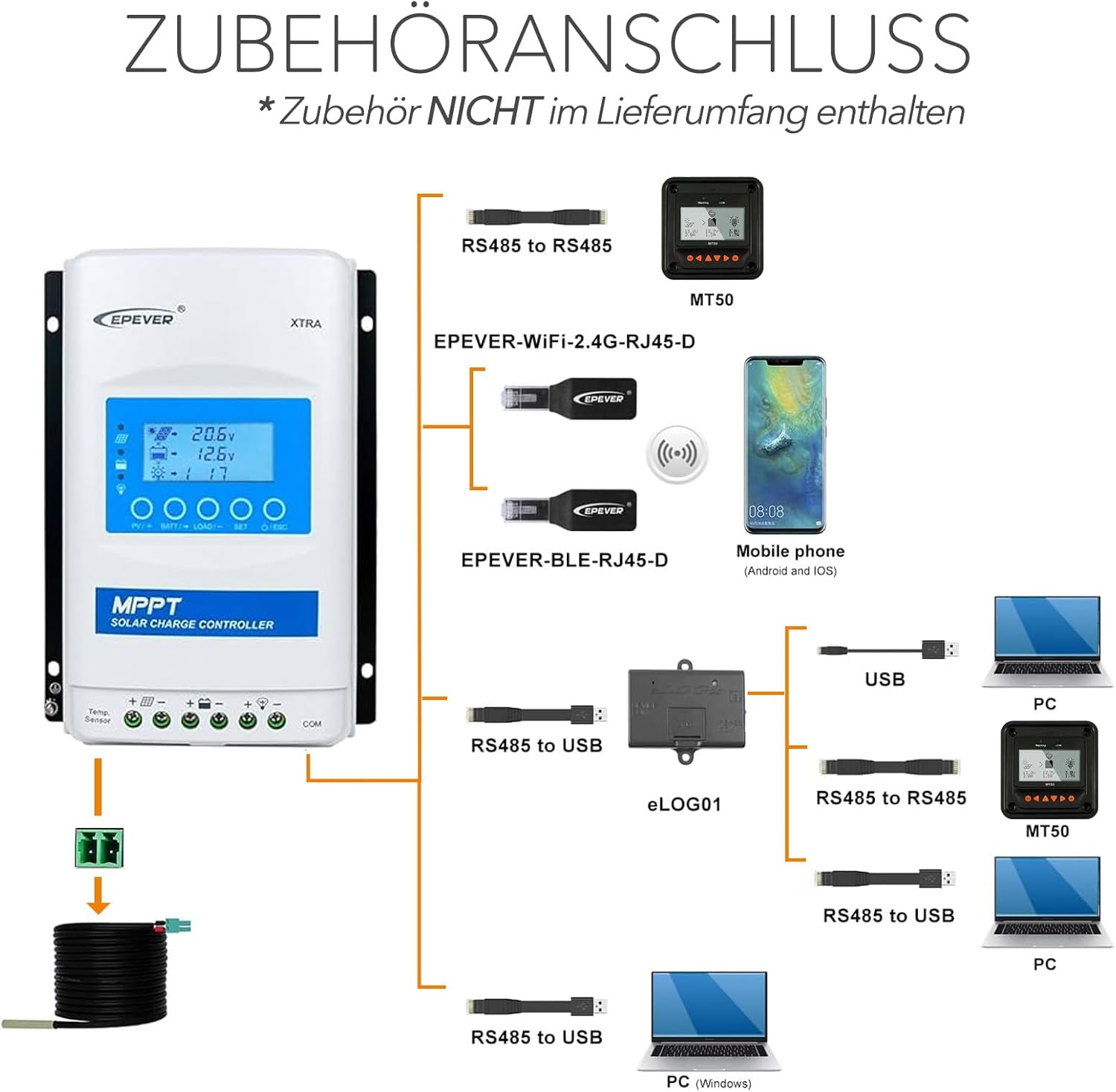
Figure 5: Diagram showing various accessory connections for the EPEVER XTRA-N controller, including RS485 to RS485, EPEVER-WIFI-2.4G-RJ45-D, EPEVER-BLE-RJ45-D for mobile phone connectivity, RS485 to USB for PC connection, and eLOG01 data logger.

Figure 6: Basic installation diagram showing connections between solar panels, the EPEVER charge controller, battery, and DC load, along with optional PC and remote meter connections.
5. Operating Instructions
5.1 LCD Display and Buttons
The LCD display provides real-time system data. Use the buttons to navigate menus and adjust settings.
- PV/+ Button: Short press to view PV parameters; long press to enter/exit setting mode.
- BATT/- Button: Short press to view battery parameters; long press to decrease values in setting mode.
- LOAD/- Button: Short press to view load parameters; long press to decrease values in setting mode.
- SET Button: Short press to confirm selection; long press to enter/exit setting mode.
- ON/OFF/ESC Button: Short press to turn load on/off; long press to exit current menu or setting.
5.2 Parameter Settings
To adjust battery type, charge voltage, or other parameters, long press the SET button to enter the setting menu. Use the PV/+ and BATT/- buttons to navigate and adjust values, and the SET button to confirm.
6. Maintenance
Regular maintenance ensures optimal performance and extends the lifespan of your charge controller.
- Check Connections: Periodically inspect all wiring connections for tightness and corrosion.
- Clean the Controller: Keep the controller clean and free of dust. Use a dry cloth for cleaning. Ensure ventilation openings are not blocked.
- Inspect Wiring: Check for any signs of wear, fraying, or damage to cables. Replace damaged cables immediately.
- Battery Inspection: Regularly check battery terminals for corrosion and ensure proper ventilation around the battery.
7. Troubleshooting
This section addresses common issues you might encounter with your EPEVER MPPT XTRA-N charge controller.
| Problem | Possible Cause | Solution |
|---|---|---|
| Controller not powering on | Battery not connected or reverse polarity; Battery voltage too low. | Check battery connections and polarity. Ensure battery voltage is above minimum operating voltage. |
| No charging from PV | PV panels not connected or reverse polarity; PV voltage too low/high; Insufficient sunlight. | Check PV connections and polarity. Verify PV voltage is within controller's operating range. Ensure adequate sunlight. |
| Load not working | Load output disabled; Overload; Short circuit; Battery low voltage disconnect. | Check load settings on display. Reduce load. Check for short circuits. Charge battery. |
| Display shows error code | Specific system fault (e.g., over-voltage, over-current, high temperature). | Refer to the full product manual for specific error code meanings and solutions. Address the underlying issue. |
8. Specifications
Detailed technical specifications for the EPEVER MPPT XTRA 1210N Solar Charge Controller.
| Parameter | Value |
|---|---|
| Nominal System Voltage | 12/24VDC Auto |
| Rated Charge Current | 10A |
| Rated Discharge Current | 10A |
| Max. PV Open Circuit Voltage | 100V |
| Max. PV Input Power (12V) | 130W |
| Max. PV Input Power (24V) | 260W |
| Operating Temperature | -25°C to +45°C |
| Enclosure Protection | IP30 |
| Dimensions (L x W x H) | 175 x 143 x 48 mm |
| Weight | 0.57 KG |
| Display Type | LCD |

Figure 7: Image showing the dimensions of the EPEVER MPPT XTRA-N charge controller: 175mm height, 143mm width, 48mm depth, and a weight of 0.57kg.
9. Warranty and Support
The EPEVER MPPT XTRA-N XTRA1210N Solar Charge Controller comes with a 2-year manufacturer's warranty from the date of purchase. This warranty covers defects in materials and workmanship under normal use.
For technical support, warranty claims, or further inquiries, please contact your local dealer or the manufacturer directly. Please have your product model number and purchase information ready when contacting support.
Certifications: CE, FCC, IEC, ETL, and RoHS compliant.
Related documentsXTRA 1210N (10A, 12/24V, max PV 100V)


Ask a question about this manual
Ask about setup, troubleshooting, compatibility, parts, safety, or missing instructions. Manuals+ will review the question and use this page’s manual context to help answer it.