
1. Introduction
The VICTOR VC8045-II is a high-performance 4½-digit bench-type digital multimeter designed for precise electrical measurements. It features a large liquid crystal display and True RMS measurement capabilities, allowing for accurate readings of various waveforms. This instrument is suitable for measuring AC and DC voltage, current, resistance, capacitance, frequency, and for testing diodes, continuity, and triodes. It includes functions such as data hold, maximum/minimum value tracking, backlight, and relative value measurement, enhancing its versatility for professional and educational applications.
2. Safety Information
Always observe the following safety precautions when operating the VICTOR VC8045-II multimeter to prevent electric shock or damage to the instrument:
- Ensure that the test leads are in good condition, free from cracks or damage, and properly connected to the instrument and the circuit under test.
- Do not exceed the maximum input ratings specified for any function. Refer to the specifications section for detailed limits.
- Disconnect power to the circuit before measuring resistance, capacitance, or continuity to avoid damage to the multimeter and the circuit.
- Use extreme caution when working with high voltages (above 30V AC RMS, 42V peak, or 60V DC) to avoid electric shock.
- Never operate the multimeter with the case open or if any parts are damaged.
- Ensure the correct function and range are selected before making any measurement.
- Replace fuses only with fuses of the specified type and rating.
3. Product Overview
The VICTOR VC8045-II is a bench-type digital multimeter featuring a clear layout for ease of use.
3.1 Front Panel
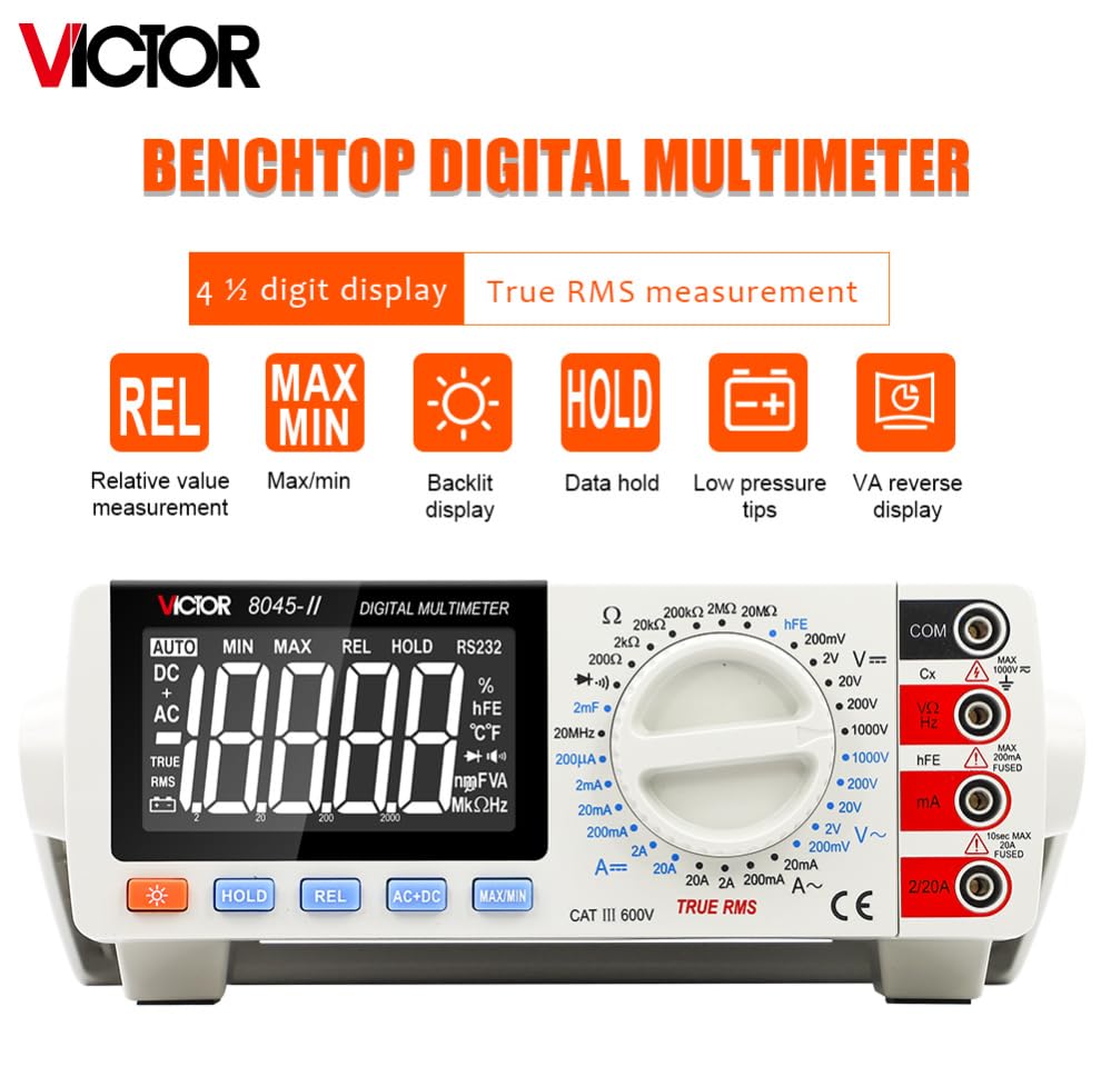
This image displays the front panel of the VICTOR VC8045-II multimeter, highlighting its large LCD, rotary function switch, and control buttons. Key features visible include the 4½-digit display, True RMS measurement indicator, and buttons for Relative Value (REL), Max/Min, Backlight, Data Hold, and Low Pressure Tips. Input terminals for COM, VΩHz, mA, and A are also clearly marked.
3.2 Display and Controls

The display is a large 4½-digit LCD with a maximum reading of 19999 counts. It features VA reverse display and various symbol indicators for units, functions, and battery status. The rotary switch allows selection of different measurement functions and ranges. Control buttons include:
- HOLD: Freezes the current reading on the display.
- REL: Activates relative measurement mode, displaying the difference from a stored reference value.
- AC+DC: Selects AC+DC measurement mode for certain functions.
- MAX/MIN: Records and displays the maximum or minimum measured value.
- Backlight: Toggles the display backlight for improved visibility in low-light conditions.
3.3 Rear Panel and Bracket

The rear panel includes the AC power input (220V/110V switchable), a power switch, and a USB port for RS232 communication. The integrated bracket allows the instrument to be positioned at an angle for better viewing or can be used for wall mounting. The fuse box design ensures protection against overload.
4. Setup
Follow these steps to set up your VICTOR VC8045-II multimeter:
- Power Connection: Connect the provided AC power cord to the multimeter's power input on the rear panel. Ensure the voltage selector switch (if present) matches your local power supply (220V or 110V). Plug the power cord into a suitable AC outlet.
- Positioning: Use the integrated bracket on the rear of the unit to position the multimeter at a comfortable viewing angle on your workbench. The bracket can also be used for wall hanging if desired.
- Test Lead Connection: Insert the black test lead into the 'COM' (Common) input jack. Insert the red test lead into the appropriate input jack for your measurement:
- For Voltage, Resistance, Capacitance, Frequency, Diode, and Continuity measurements: Use the 'VΩHz' jack.
- For Current measurements (up to 200mA): Use the 'mA' jack.
- For High Current measurements (up to 20A): Use the 'A' jack.
- Power On: Flip the power switch on the rear panel to the 'ON' position. The display should illuminate.
5. Operating Instructions
This section details how to perform various measurements using the VICTOR VC8045-II multimeter.
5.1 General Operation

This image illustrates the detailed view of the LCD display and the rotary range knob. The display shows the 4½-digit precision and various symbols. The rotary knob is clearly marked with distinct ranges and functions, indicating maximum value displays and warning signs for safe operation.
- Function Selection: Rotate the central knob to select the desired measurement function (e.g., DCV, ACV, Resistance, Current).
- Range Selection: The multimeter operates in manual range mode. After selecting a function, rotate the knob further to select the appropriate measurement range. Always start with the highest range if the approximate value is unknown to prevent overload.
- Backlight: Press the 'Backlight' button to turn the display backlight on or off.
- Data Hold: Press the 'HOLD' button to freeze the current reading on the display. Press again to release.
- Relative Measurement (REL): Press the 'REL' button to store the current reading as a reference. Subsequent measurements will display the difference from this reference. Press again to exit relative mode.
- Maximum/Minimum (MAX/MIN): Press the 'MAX/MIN' button to enter this mode. The multimeter will continuously track and display the maximum or minimum value measured. Pressing the button cycles between MAX, MIN, and normal display.
5.2 Voltage Measurement (DCV/ACV)
- Insert the black test lead into the 'COM' jack and the red test lead into the 'VΩHz' jack.
- Rotate the function knob to the desired DCV (V=) or ACV (V~) range.
- Connect the test leads in parallel across the component or circuit to be measured.
- Read the voltage value on the display.
5.3 Current Measurement (DCA/ACA)
- IMPORTANT: To measure current, the multimeter must be connected in series with the circuit. Disconnect power to the circuit before connecting the multimeter.
- Insert the black test lead into the 'COM' jack. For currents up to 200mA, insert the red test lead into the 'mA' jack. For currents up to 20A, insert the red test lead into the 'A' jack.
- Rotate the function knob to the desired DCA (A=) or ACA (A~) range.
- Break the circuit and connect the test leads in series with the load.
- Apply power to the circuit and read the current value on the display.
5.4 Resistance Measurement (Ω)
- IMPORTANT: Ensure the circuit is completely de-energized before measuring resistance.
- Insert the black test lead into the 'COM' jack and the red test lead into the 'VΩHz' jack.
- Rotate the function knob to the 'Ω' range.
- Connect the test leads across the component whose resistance is to be measured.
- Read the resistance value on the display.
5.5 Capacitance Measurement (CAP)
- IMPORTANT: Ensure the capacitor is fully discharged before measurement to prevent damage to the multimeter.
- Insert the black test lead into the 'COM' jack and the red test lead into the 'VΩHz' jack.
- Rotate the function knob to the 'CAP' (Capacitance) range.
- Connect the test leads across the capacitor.
- Read the capacitance value on the display.
5.6 Frequency Measurement (Hz)
- Insert the black test lead into the 'COM' jack and the red test lead into the 'VΩHz' jack.
- Rotate the function knob to the 'Hz' (Frequency) range.
- Connect the test leads across the signal source.
- Read the frequency value on the display.
5.7 Diode Test
- IMPORTANT: Ensure the diode is disconnected from the circuit and de-energized.
- Insert the black test lead into the 'COM' jack and the red test lead into the 'VΩHz' jack.
- Rotate the function knob to the 'Diode' symbol.
- Connect the red lead to the anode and the black lead to the cathode of the diode. A forward voltage drop will be displayed. Reverse the leads; the display should show 'OL' (Open Loop) for a good diode.
5.8 Continuity Test
- IMPORTANT: Ensure the circuit is completely de-energized before testing continuity.
- Insert the black test lead into the 'COM' jack and the red test lead into the 'VΩHz' jack.
- Rotate the function knob to the 'Continuity' symbol (often shared with Diode test, indicated by a buzzer icon).
- Connect the test leads across the component or wire to be tested. If continuity exists (resistance below a certain threshold), the buzzer will sound.
5.9 Triode Test (hFE)
- Insert the black test lead into the 'COM' jack and the red test lead into the 'VΩHz' jack.
- Rotate the function knob to the 'hFE' range.
- Insert the transistor leads into the appropriate NPN or PNP sockets on the front panel.
- Read the hFE (DC current gain) value on the display.
6. Maintenance
Proper maintenance ensures the longevity and accuracy of your multimeter.
- Cleaning: Wipe the case with a soft, damp cloth. Do not use abrasives or solvents.
- Fuse Replacement: The multimeter is equipped with overload protection and fuses. If a current measurement function stops working, the fuse may need replacement. Refer to the specifications for the correct fuse type and rating. Always disconnect power and test leads before opening the fuse compartment.
- Storage: When not in use for extended periods, store the multimeter in a dry, dust-free environment.
7. Troubleshooting
If you encounter issues with your VICTOR VC8045-II, refer to the following common troubleshooting steps:
- No Display: Check if the power cord is securely connected and the power switch is in the 'ON' position. Ensure the AC power outlet is functional.
- Incorrect Readings: Verify that the correct function and range are selected for the measurement. Ensure test leads are properly connected and making good contact with the circuit. Check if the circuit under test is de-energized for resistance, capacitance, or continuity measurements.
- 'OL' (Overload) Display: This indicates that the input value exceeds the selected range. Select a higher range or ensure the input is within the multimeter's maximum limits.
- Current Measurement Not Working: Check the fuse for the current input jack. A blown fuse will prevent current measurements.
- Buzzer Not Sounding in Continuity Test: Ensure the circuit is de-energized and the resistance is below the continuity threshold.
8. Specifications
The following tables detail the technical specifications of the VICTOR VC8045-II Digital Multimeter.
8.1 Basic Functions and Accuracy

This image presents a table outlining the basic functions, measurement ranges, basic accuracy, and resolution for DC Voltage, AC Voltage, DC Current, AC Current, Resistance, Frequency, and Capacitance.
| Basic Function | Range | Basic Accuracy | Resolution |
|---|---|---|---|
| DC Voltage | 200mV/2V/20V/200V | ±(0.05%+5) | 10uV/100uV/1mV/10mV |
| 1000V | ±(0.1%+5) | 100mV | |
| AC Voltage | 200mV | 40Hz-1kHz:±(0.7%+30) 1kHz-10kHz:±(2%+30) 10kHz-20kHz:±(3%+60) 20kHz-50kHz:±(10%+250) | 10uV |
| 2V | 40Hz-1kHz:±(0.5%+30) 1kHz-10kHz:±(2%+30) 10kHz-20kHz:±(5%+60) | 100uV | |
| 20V | 40Hz-1kHz:±(0.5%+30) | 1mV | |
| 200V | 40Hz-1kHz:±(0.5%+30) | 10mV | |
| 1000V | 40Hz-200Hz:±(0.8%+10) 200Hz-400Hz:±(1.2%+80) | 100mV | |
| DC Current | 200uA /2mA /20mA/200mA | ±(0.35%+10) | 0.01uA/0.1uA/1uA/10uA |
| 2A | ±(0.8%+10) | 100uA | |
| 20A | ±(2.0%+15) | 1mA | |
| AC Current | 200mA/2A | ±(0.8%+80) | 1uA/10uA/100uA |
| 20A | ±(2.5%+35) | 1mA | |
| Resistance | 200Ω/2kΩ/20kΩ/200kΩ/2MΩ | ±(0.5%+30) | 0.01Ω/0.1Ω/1Ω/10Ω/100Ω |
| 20MΩ | ±(0.6%+50) | 1kΩ | |
| Frequency | 20Hz~200kHz/200kHz~2MHz/2MHz~20MHz | ±(0.1%+3) | 0.01Hz/0.1Hz/0.001MHz/0.01MHz |
| Capacitance | 20nF/200nF/2uF/20uF | ±(3.5%+20) | 1pF/10pF/100pF/1nF |
| 200uF/2000uF | ±(5%+30) | 10nF/100nF |
8.2 General Specifications and Special Functions

This image displays a table detailing the special functions available on the multimeter, such as Diode test, Frequency, Resistance, Triode test, Continuity buzzer, and Overload protection. It also lists general specifications including ACV frequency response, operation method, maximum display count, dimensions, weight, and power requirements.
| Feature | Value |
|---|---|
| Diode test | ✓ |
| Frequency | ✓ |
| Resistance | ✓ |
| Triode test | ✓ |
| Continuity buzzer | ✓ |
| Overload protection | ✓ |
| ACV frequency response | 50kHz |
| Operation way | Manual range |
| Max. Display | 19999 |
| Dimension | 260mm*220mm*82mm |
| Weight | Approx:1Kg |
| Power | AC220V/110V 47Hz-62Hz |
9. Warranty and Support
The VICTOR VC8045-II Digital Multimeter comes with a standard manufacturer's warranty against defects in materials and workmanship. For warranty claims, technical support, or service inquiries, please contact your authorized dealer or the manufacturer's customer service department. Keep your purchase receipt as proof of purchase.


