
1. Introduction
The Multispan UTR-433 is a versatile universal programmable timer designed for various industrial and scientific applications. This device offers precise timing control with configurable input, output, and operating modes. This manual provides detailed instructions for the installation, operation, and maintenance of your UTR-433 timer.
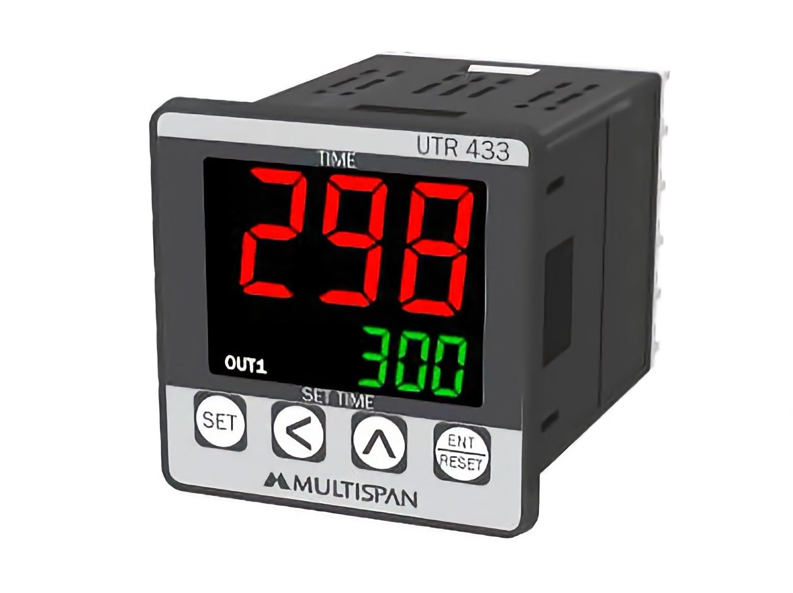
Figure 1: Front view of the Multispan UTR-433 Universal Programmable Timer, showing the display and control buttons.
2. Specifications
This section details the technical specifications of the UTR-433 timer.
2.1 Input and Output Specifications
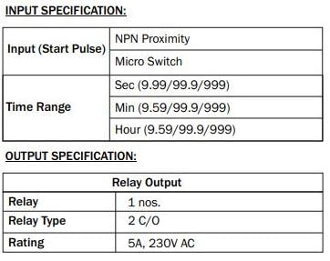
Figure 2: Detailed input and output specifications, including start pulse types, time ranges, relay type, and rating.
- Input (Start Pulse): Configurable for Micro Switch, Limit Switch, or Proximity (NPN).
- Time Range: Configurable in Seconds (9.99, 99.9, 999), Minutes (9.59, 99.9, 999), or Hours (9.59, 99.9, 999).
- Output: 1 Relay, 2 Changeover (C/O) contacts.
- Relay Rating: 5A at 230V AC (Resistive Load).
2.2 Display, Keys, Dimensions, and General Specifications
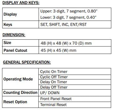
Figure 3: Information on the timer's display, control keys, physical dimensions, and general operating modes.
- Display: Upper 3-digit, 7-segment, 0.80"; Lower 3-digit, 7-segment, 0.40".
- Keys: SET, SHIFT, INC, ENT/RST for programming and control.
- Size (HxWxD): 48 x 48 x 70 mm.
- Panel Cutout: 45 x 45 mm.
- Operating Modes: Configurable for Delayed ON, Delayed OFF, Cyclic On Timer, Cyclic Off Timer.
- Count Direction: Configurable for UP or DOWN counting.
- Memory: Configurable YES/NO option for retaining settings.
- Reset Options: Front Panel Reset and Terminal Reset available.
2.3 Auxiliary Supply and Environmental Conditions
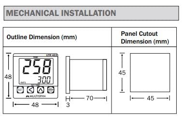
Figure 4: Details regarding the power supply requirements and environmental operating limits.
- Supply Voltage: 100-270V AC (SMPS), 50/60Hz.
- Power Consumption: Approximately 4 VA @ 230V AC MAX.
- Operating Temperature: 0°C to 55°C.
- Relative Humidity: Up to 95% RH (non-condensing).
- Protection Level: IP-65 (Front side) as per IS/IEC 60529:2001.
3. Installation
Proper installation is crucial for the safe and reliable operation of the UTR-433 timer.
3.1 Mechanical Installation
The UTR-433 timer is designed for panel mounting. Ensure the panel cutout dimensions match the device specifications.
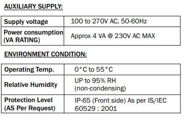
Figure 5: Mechanical installation diagram showing the outline dimensions of the timer and the required panel cutout dimensions.
- Create a panel cutout of 45 mm (Height) x 45 mm (Width).
- Insert the timer into the cutout from the front.
- Secure the timer using the provided mounting clamps from the rear of the panel.
3.2 Electrical Connection
Refer to the terminal connection diagram for correct wiring. Ensure all connections are secure and comply with local electrical codes.
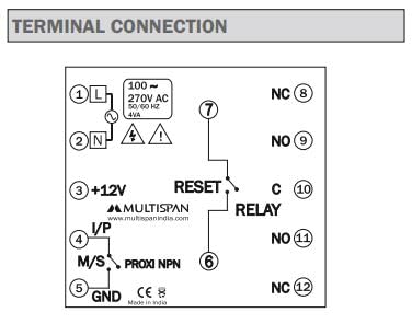
Figure 6: Terminal connection diagram illustrating the wiring points for power, input, reset, and relay output.
- Terminal 1 (L): Connect to Live (Phase) of the 100-270V AC supply.
- Terminal 2 (N): Connect to Neutral of the 100-270V AC supply.
- Terminal 3 (+12V): +12V DC auxiliary output for input sensors.
- Terminal 4 (I/P): Input terminal for start pulse (Micro Switch, Limit Switch, Proximity NPN).
- Terminal 5 (GND): Ground connection for input sensors and +12V return.
- Terminal 6 (RESET): External reset input.
- Terminal 7 (RESET): External reset input. (Note: Terminals 6 and 7 are for external reset connection).
- Terminal 8 (NC): Normally Closed contact of Relay 1.
- Terminal 9 (NO): Normally Open contact of Relay 1.
- Terminal 10 (C): Common contact of Relay 1.
- Terminal 11 (NO): Normally Open contact of Relay 2 (if applicable, or second NO for 2C/O).
- Terminal 12 (NC): Normally Closed contact of Relay 2 (if applicable, or second NC for 2C/O).
Important: Disconnect power before making any electrical connections. Incorrect wiring can damage the device or cause electrical hazards.
4. Operation
This section describes how to configure and operate your UTR-433 timer.
4.1 Key Functions
- SET: Enters programming mode or confirms a setting.
- SHIFT: Moves cursor or shifts digits during parameter setting.
- INC (Increment): Increases the value of the selected digit or parameter.
- ENT/RST (Enter/Reset): Confirms a setting or initiates a reset function.
4.2 Programming Modes
The UTR-433 supports several operating modes. To select a mode:
- Press the SET key to enter programming mode.
- Navigate through the parameters using SHIFT and INC until you reach the 'Operating Mode' setting.
- Use INC to select one of the following modes:
- Delayed ON: The output relay activates after a set delay time once the input pulse is received.
- Delayed OFF: The output relay deactivates after a set delay time once the input pulse is received.
- Cyclic On Timer: The relay cycles ON for a set time, then OFF for a set time, continuously.
- Cyclic Off Timer: The relay cycles OFF for a set time, then ON for a set time, continuously.
- Press ENT/RST to confirm the selection and exit programming mode.
4.3 Time Range Configuration
The timer's range can be set in seconds, minutes, or hours with varying decimal precision.
- Enter programming mode using the SET key.
- Locate the 'Time Range' parameter.
- Use INC to cycle through options like 9.99 Sec, 99.9 Sec, 999 Sec, 9.59 Min, 99.9 Min, 999 Min, 9.59 Hrs, 99.9 Hrs, 999 Hrs.
- Confirm your selection with ENT/RST.
4.4 Counting Direction and Memory
- Counting Direction: The timer can be configured to count UP or DOWN. Access this setting in programming mode and use INC to toggle between options.
- Memory: The memory function (YES/NO) determines if the timer retains its count or state after a power cycle. Configure this setting in programming mode as needed.
4.5 Reset Options
- Front Panel Reset: Pressing the ENT/RST key on the front panel can reset the timer, depending on configuration.
- Terminal Reset: An external reset signal can be applied to the dedicated reset terminals (6 and 7) for remote resetting.
5. Maintenance
The UTR-433 timer is designed for reliable operation with minimal maintenance.
- Cleaning: Keep the timer's display and housing clean. Use a soft, dry cloth. Avoid abrasive cleaners or solvents.
- Environmental Conditions: Ensure the operating environment adheres to the specified temperature (0°C to 55°C) and humidity (up to 95% RH non-condensing) limits to prevent damage and ensure longevity.
- Inspection: Periodically check electrical connections for tightness and signs of wear.
6. Troubleshooting
If you encounter issues with your UTR-433 timer, consider the following basic troubleshooting steps:
- No Power/Display: Check the auxiliary supply connections (Terminals 1 and 2) and ensure the voltage is within the 100-270V AC range. Verify the power source is active.
- Incorrect Timing: Review the programmed time range and operating mode settings. Ensure the input pulse is correctly detected.
- Relay Not Activating: Check the relay output connections (Terminals 8, 9, 10, 11, 12). Verify the operating mode and set time are correct, and the timer has reached its activation condition.
- Input Not Detected: Ensure the input sensor (Micro Switch, Limit Switch, Proximity) is correctly wired to Terminals 4 and 5 (GND) and is functioning properly. Check the +12V supply if using an active sensor.
- Device Not Responding: Attempt a front panel reset. If the issue persists, power cycle the device.
For persistent issues or complex problems, contact Multispan technical support.
7. Warranty and Support
This product is manufactured by MULTISPAN. For warranty information, technical assistance, or service, please contact your supplier or the manufacturer directly. Keep your purchase receipt as proof of purchase.