
1. Introduction
Thank you for choosing the BSIDE A1 Mini Digital Multimeter. This compact and intelligent device is designed for safe and accurate electrical measurements, suitable for both professionals and DIY enthusiasts. It features automatic range selection, a clear 3-result display, and non-contact voltage detection. Please read this manual thoroughly before use to ensure proper operation and safety.
2. Safety Information
To prevent possible electrical shock, fire, or personal injury, please follow these safety guidelines:
- Always adhere to local and national safety codes.
- Do not use the multimeter if it appears damaged or if the test leads are damaged.
- Do not apply more than the rated voltage, as marked on the multimeter, between the terminals or between any terminal and earth ground.
- Use caution when working with voltages above 30V AC RMS, 42V peak, or 60V DC. These voltages pose a shock hazard.
- Keep your fingers behind the finger guards on the test probes during use.
- Replace the batteries when the low battery indicator appears to ensure accurate readings.
- Do not operate the multimeter in explosive gas, vapor, or dusty environments.
- Ensure the multimeter is in the correct function and range for the measurement.
- Disconnect power to the circuit and discharge all high-voltage capacitors before testing resistance or continuity.
3. Package Contents
Verify that all items are present in the package:
- 1 x BSIDE A1 Smart Multimeter
- 1 x Pair of Test Leads
- 2 x AAA Batteries
- 1 x Carrying Case
- 1 x Screwdriver
- 1 x User Manual

Figure 3.1: Contents of the BSIDE A1 Mini Digital Multimeter package.
4. Product Overview
4.1 Key Features
- Smart Auto Mode: Automatically identifies and measures AC/DC voltage, resistance, frequency, and continuity.
- 3-Result Display: Large LCD with red/green backlight shows tested value, analog bar, and frequency/ambient temperature simultaneously.
- Non-Contact Voltage (NCV) Detection: Adjustable sensitivity for detecting live wires without physical contact, with triple-mode alarm.
- Live/Neutral Wire Check: Distinguishes between live and neutral wires.
- Built-in Flashlight: Assists in working in dimly lit areas.
- Compact Design: Pocket-sized for portability and ease of use.
- Additional Functions: Auto power-off, data hold, low battery indication.
4.2 Display and Controls

Figure 4.1: The multimeter features a large LCD with selectable red or green backlight for clear visibility.

Figure 4.2: The integrated LED flashlight illuminates the work area for convenience.
5. Setup
5.1 Battery Installation
- Locate the battery compartment on the back of the multimeter.
- Use the provided screwdriver to open the battery cover.
- Insert two AAA 1.5V batteries, ensuring correct polarity (+ and -).
- Replace the battery cover and secure it with the screw.
6. Operating Instructions
6.1 Power On/Off
Press the POWER button to turn the multimeter on or off. The device will automatically enter Smart Auto Mode upon power-on.
6.2 Smart Auto Mode
In Smart Auto Mode, the multimeter automatically detects and measures AC/DC voltage, resistance, frequency, and continuity. This mode simplifies operation for beginners.

Figure 6.1: The display indicates the active measurement function, including the automatic mode.
6.3 Specific Measurements
While in Smart Auto Mode, the multimeter will attempt to identify the measurement type. For specific functions or to manually select a mode, press the SEL button to cycle through available modes if applicable.
6.3.1 Voltage Measurement (AC/DC)
- Connect the red test lead to the 'INPUT' terminal and the black test lead to the 'COM' terminal.
- Touch the test probes to the circuit points where voltage is to be measured.
- The display will show the voltage reading. The multimeter automatically distinguishes between AC and DC voltage.
6.3.2 Resistance Measurement
- Ensure the circuit is de-energized before measuring resistance.
- Connect the test leads as described for voltage measurement.
- Touch the test probes across the component or circuit section to be measured.
- The display will show the resistance value in Ohms (Ω).
6.3.3 Continuity Test
- Ensure the circuit is de-energized.
- Connect the test leads as described for voltage measurement.
- Touch the test probes to the two points you want to check for continuity.
- If resistance is below 30Ω, the buzzer will sound, indicating continuity.
6.3.4 Frequency Measurement
- Connect the test leads to the circuit.
- The display will show the frequency in Hertz (Hz).
6.4 V-Alert (Non-Contact Voltage) Detection
The V-Alert function allows detection of AC voltage without direct contact with conductors.
- Press the V-Alert button to activate this mode.
- Move the top of the multimeter near the wire or outlet to be tested.
- The display will show 'Lo' (low sensitivity) or 'Hi' (high sensitivity) and an alarm will sound, with the backlight changing color, indicating the presence of AC voltage.

Figure 6.2: V-Alert function in use, detecting voltage without direct contact.
6.5 Live/Neutral Wire Check
This function helps identify live and neutral wires in an AC circuit.
- Activate the Live Wire Check mode (often integrated with V-Alert or a dedicated button).
- Insert the red test probe into the socket or touch it to the wire.
- The multimeter will indicate if the wire is live (stronger signal, often red backlight) or neutral (weaker signal, often green backlight).

Figure 6.3: Distinguishing between neutral and live wires using the multimeter's detection feature.
6.6 Data Hold
Press the HOLD button (if available, often integrated with SEL button) to freeze the current reading on the display. Press again to release.

Figure 6.4: The multimeter is suitable for various applications, including automotive electrical checks.
7. Maintenance
7.1 Cleaning
Wipe the case with a damp cloth and mild detergent. Do not use abrasives or solvents. Ensure the multimeter is off and disconnected from any circuits before cleaning.
7.2 Battery Replacement
When the low battery indicator appears on the display, replace the batteries as described in Section 5.1. Remove batteries if the multimeter is not used for an extended period.
8. Troubleshooting
- No Display: Check battery installation and ensure batteries are not depleted. Replace if necessary.
- Inaccurate Readings: Ensure test leads are properly connected. Check battery level. Verify the correct measurement mode is selected (if not in auto mode).
- No Continuity Beep: Ensure the circuit is de-energized. Check if the resistance is above 30Ω.
- V-Alert Not Working: Ensure the V-Alert function is activated. Check for strong electromagnetic interference in the environment.
9. Specifications
| Parameter | Value |
|---|---|
| Model Number | A1 Smart Multimeter de poche |
| Display | 2000 Counts, 2.2-inch LCD |
| DC Voltage | 500V 0.01V ± (0.8%+3) |
| AC Voltage | 500V 0.01V ± (1.2%+5) |
| Resistance | 0Ω-10MΩ 1Ω ± (1.2%+3) |
| Frequency | 1000Hz 0.1Hz ± (2.0%+3) |
| Continuity | Buzzer sounds if resistance < 30Ω |
| V-Alert (NCV) | 90V-1000V/6V-1000V AC Voltage |
| Live Wire Check | Yes |
| Power Source | 2 x 1.5V AAA Batteries (included) |
| Dimensions | 127 x 42 x 25 mm (5 x 1.65 x 0.98 inches) |
| Weight | 67 grams (2.36 ounces) |
| Operating Style | Mini automatic digital multimeter |
| Country of Origin | China |
10. Warranty and Support
For warranty information or technical support, please refer to the contact details provided with your purchase or visit the official BSIDE website. Keep your purchase receipt as proof of purchase.
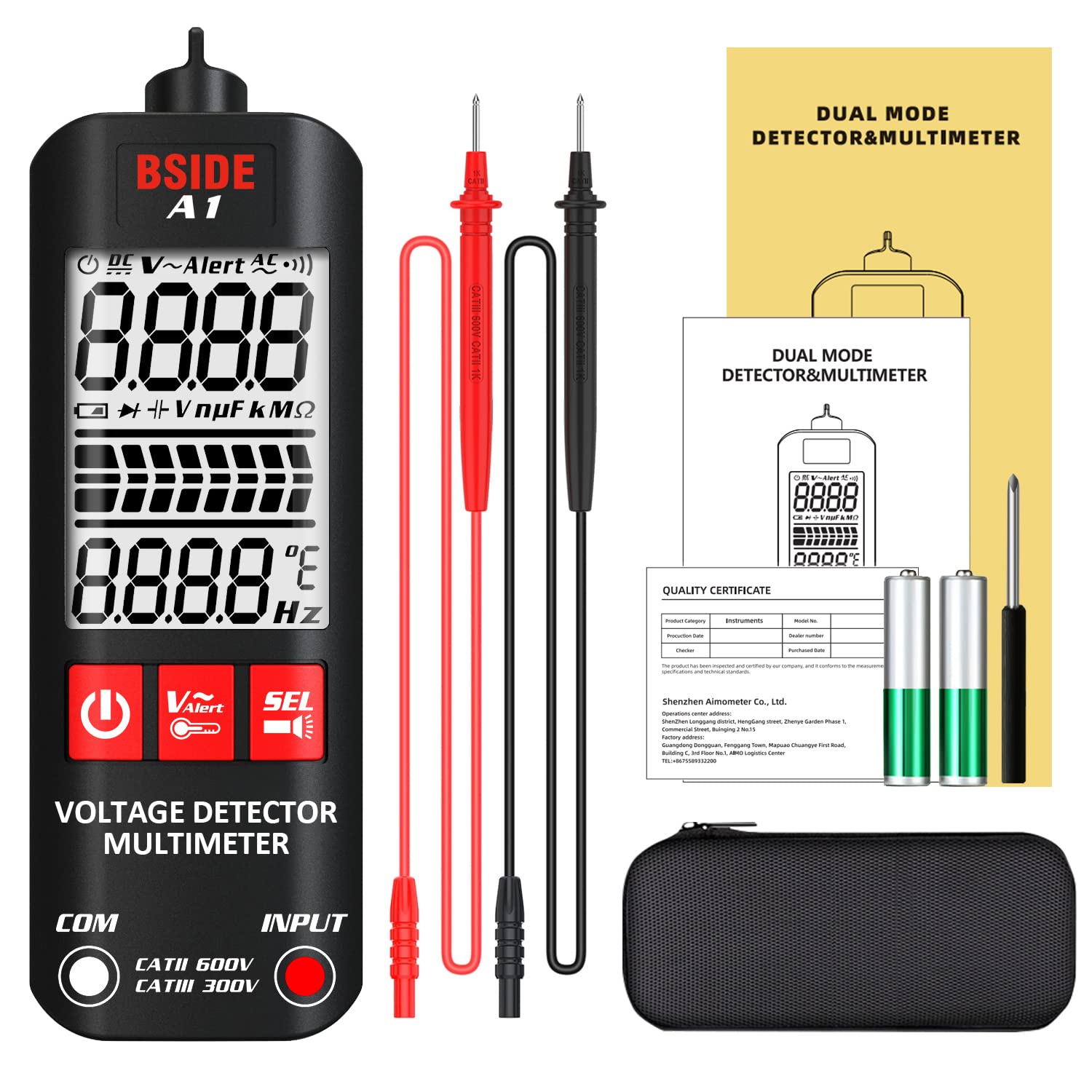
Figure 10.1: The complete BSIDE A1 Mini Digital Multimeter package, ready for use.


