
Introduction
This user manual provides detailed instructions for the operation, maintenance, and troubleshooting of the Bewinner Inverter Refrigerator Testing Instrument. This versatile tool is designed for diagnosing and repairing various components of inverter refrigerators and air conditioning systems, including inverter compressors, solenoid valves, and fan motors.
Product Overview
The Bewinner Inverter Refrigerator Testing Instrument is a comprehensive diagnostic tool for refrigeration and air conditioning repair. It features a clear display for frequency, voltage, and current, and supports various testing functions.
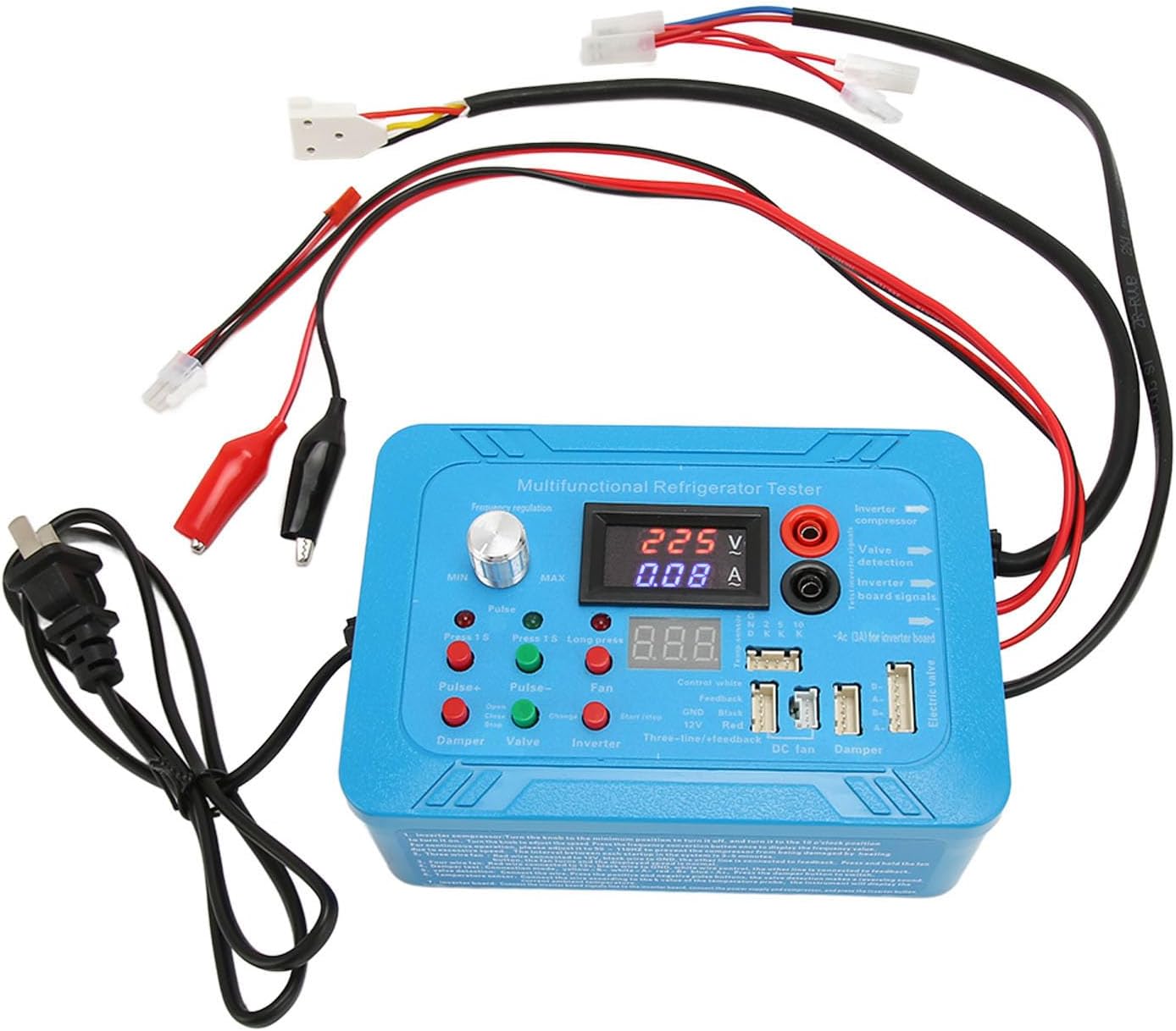
Figure 1: Front view of the Bewinner Inverter Refrigerator Testing Instrument, showing the display, control knob, and various connection ports.

Figure 2: Labeled diagram of the testing instrument, highlighting key components such as frequency adjustable knob, voltage display, current display, and various detection ports.
- 1. Frequency Adjustable: Knob for adjusting the output frequency.
- 2. Voltage Display: Shows the current voltage reading.
- 3. Current Display: Shows the current amperage reading.
- 4. Frequency Conversion Compressor Inspection: Port for testing inverter compressors.
- 5. Single Line Frequency Conversion Board Detection: For single-line inverter board testing.
- 6. Pulse Solenoid Valve Detection: For testing pulse solenoid valves.
- 7. Main Board To Solenoid Valve Output Detection: For checking output from mainboard to solenoid valve.
- 8. Constant Frequency Compressor Power Supply Observation Current: For observing current of fixed frequency compressors.
- 9. Double Wire Frequency Conversion Board Detection: For double-wire inverter board testing.
- 10. 6 Pin Electric Valve Detection: For 6-pin electric valve testing.
- 11. 5 Pin Electric Valve Detection: For 5-pin electric valve testing.
- 12. Electric Valve Stuck Repair: Function for repairing stuck electric valves.
- 13. Home Air Conditioning Electronic Expansion Valve Drive Detection: For testing electronic expansion valves in AC units.
- 14. Single and Double Damper Detection: For testing single and double dampers.
- 15. Air Door Heating Wire Power Supply: Power supply for air door heating wires.
- 16. 3 Wire Fan Detection: For testing 3-wire fans.
- 17. 4 Wire Fan Detection: For testing 4-wire fans.
Setup
Before using the instrument, ensure all connections are secure and the power supply is stable. The device operates on a standard power outlet.
Package Contents:

Figure 3: The complete package contents, including the main testing unit, various wiring harnesses, and alligator clips for versatile connections.
The package typically includes the main testing unit, a power cord, and various connection cables/adapters for different testing scenarios. Familiarize yourself with the different wiring terminals and their corresponding functions as shown in Figure 2.

Figure 4: A close-up view of a typical 3-pin connector cable, often used for fan detection or other specific component connections.

Figure 5: Alligator clip test leads, essential for connecting to various terminals and components for testing purposes.
Operating Instructions
This section details the procedures for using the testing instrument for various diagnostic tasks.
1. Inverter Compressor Detection:
- Connect the inverter compressor to the designated port on the tester (refer to Figure 2, item 4).
- Adjust the frequency using the "Frequency Adjustable" knob (Figure 2, item 1) to simulate different operating conditions.
- Observe the voltage and current readings on the display (Figure 2, items 2 & 3) to assess compressor performance.
2. Solenoid Valve Detection:
The instrument supports testing of both pulse solenoid valves and mainboard output to solenoid valves.
- For pulse solenoid valve detection, connect the valve to the corresponding port (Figure 2, item 6).
- For mainboard output detection, connect the mainboard output to the specified port (Figure 2, item 7).
- Monitor the instrument's display for proper signal and operation.
3. Fan Motor Detection (3-wire and 4-wire):
The tester can diagnose both 3-wire and 4-wire fan motors commonly found in refrigerators and air conditioners.
- Connect the fan motor to the appropriate 3-wire (Figure 2, item 16) or 4-wire (Figure 2, item 17) fan detection port.
- Activate the test function and observe the fan's operation and any readings on the display.
4. Compressor Cylinder Jamming Repair:
This function assists in attempting to repair slight compressor jams caused by overheating. The instrument will attempt to drive the compressor cylinder three times.
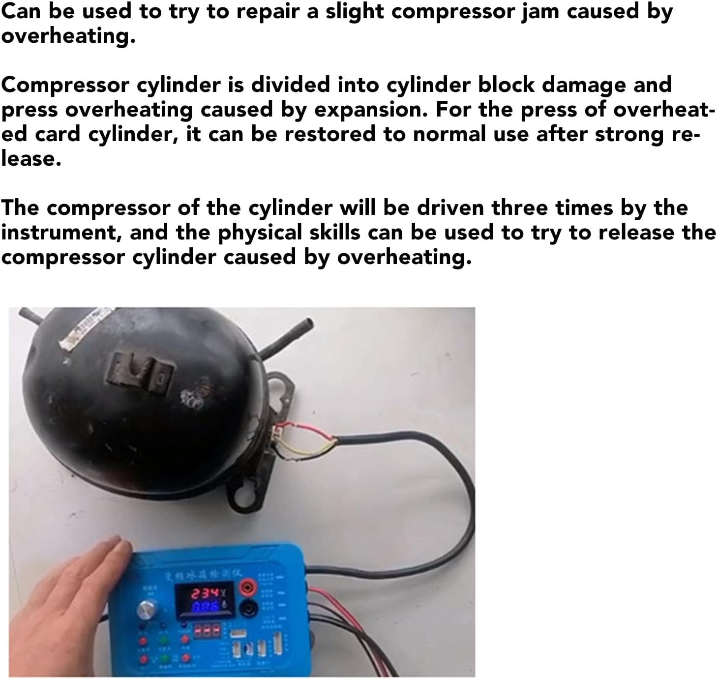
Figure 6: The testing instrument connected to a refrigerator compressor, demonstrating the setup for diagnosing or attempting to repair a jammed compressor.
If the compressor does not start after three attempts, a buzzer alarm will sound, indicating a persistent issue.

Figure 7: A diagram illustrating various motor types that can be tested, including washing machine motors (3-wire permanent magnet synchronous, 3-wire DC brushless, 3-phase asynchronous) and air conditioning compressor pseudo load drives.
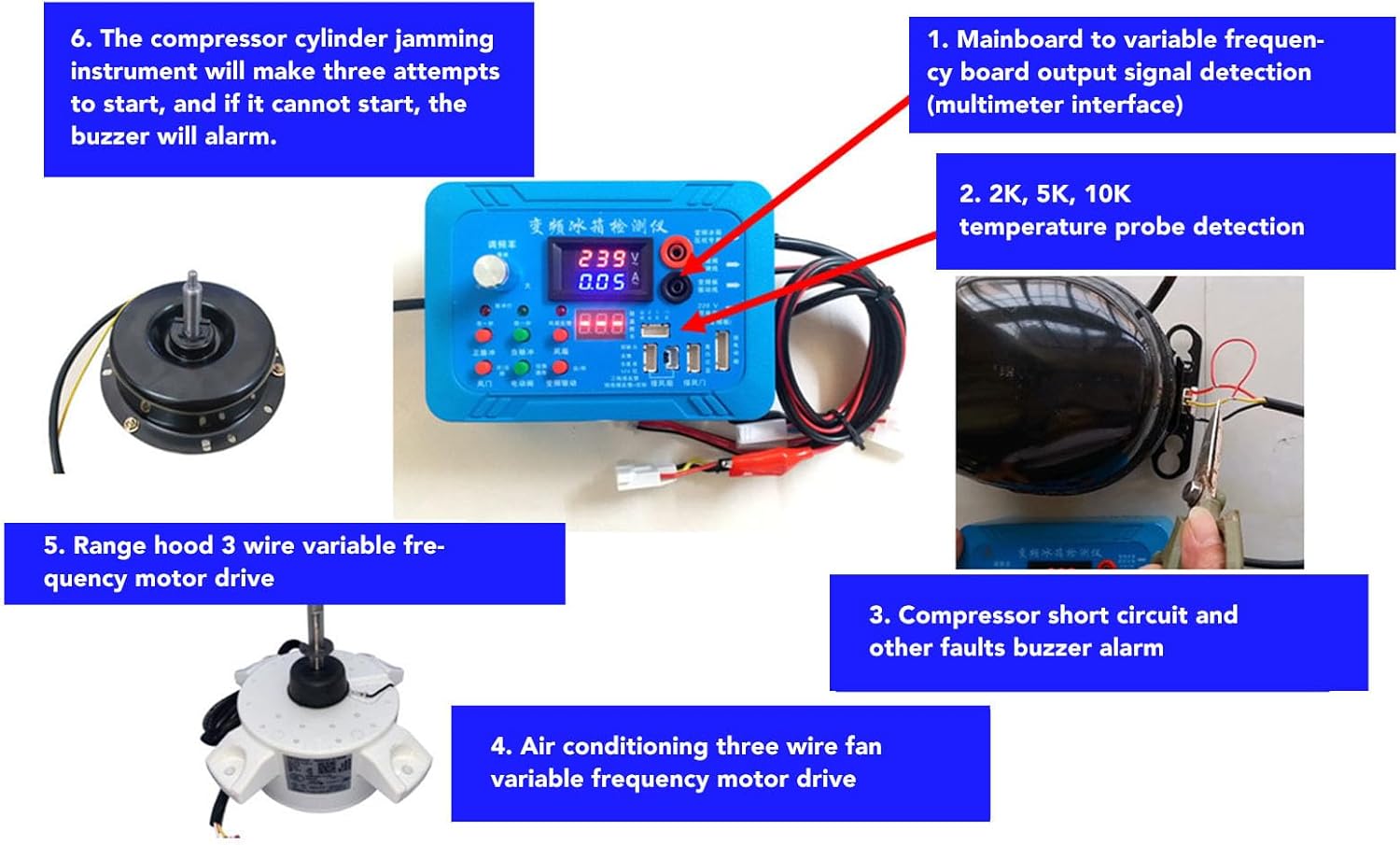
Figure 8: A diagram detailing connections for temperature probe detection (2K, 5K, 10K), mainboard to variable frequency board output signal detection, and various fan motor drives (range hood 3-wire, air conditioning 3-wire).
Maintenance
To ensure the longevity and accuracy of your testing instrument, follow these maintenance guidelines:
- Cleaning: Wipe the instrument with a soft, dry cloth. Do not use abrasive cleaners or solvents.
- Storage: Store the device in a cool, dry place away from direct sunlight and extreme temperatures.
- Cable Care: Inspect all cables and connectors regularly for signs of wear or damage. Replace any damaged components immediately.
- Avoid Liquids: Keep the instrument away from water and other liquids to prevent electrical damage.
Troubleshooting
This section addresses common issues you might encounter and their potential solutions.
| Problem | Possible Cause | Solution |
|---|---|---|
| Instrument does not power on. | No power supply; faulty power cord. | Ensure power cord is securely plugged in. Test outlet with another device. Replace power cord if damaged. |
| No readings on display. | Incorrect connection; component not functioning. | Verify all connections are correct and secure. Ensure the component being tested is operational. |
| Buzzer alarm sounds during test. | Compressor short circuit; other fault detected. | Refer to the specific test function for alarm conditions. Check for short circuits or other component failures. |
| Inaccurate readings. | Loose connections; damaged test leads. | Check all connections for tightness. Inspect test leads for damage and replace if necessary. |
Specifications
- Brand: Bewinner
- Model: B0CJMHXH1R
- Power Source: Corded Electric
- Color: Blue
- Operating System: For Windows operating system (internal, not user-accessible)
- Key Features: Inverter compressor detection, single line inverter board detection, pulse solenoid valve detection, solenoid valve mainboard output detection, fixed frequency compressor power supply current observation, 6-pin and 5-pin electric valve detection, electric valve stuck repair, household air conditioning electronic expansion valve drive detection, 3-wire fan detection, 4-wire fan detection, 2K/5K/10K temperature probe detection, compressor short circuit and fault buzzer alarms.
Warranty and Support
For warranty information and technical support, please refer to the official Bewinner website or contact their customer service. Protection plans may also be available for extended coverage.
- Manufacturer: Bewinner
- Amazon Store: Visit the Bewinner Store on Amazon