1. Introduction
Thank you for choosing the GOLDEN BLUE PN200 Digital Clamp Meter Multimeter. This device is a versatile and accurate tool designed for various electrical measurements, including AC/DC current, AC/DC voltage, resistance, capacitance, frequency, diode testing, and non-contact voltage (NCV) detection. With its 4000-count display and robust design, it is suitable for both professional and DIY electrical troubleshooting and maintenance. Please read this manual thoroughly before use to ensure safe and proper operation.
2. Safety Information
To prevent possible electrical shock, fire, or personal injury, please read all safety information before you use the product.
- Always ensure the meter is in good working condition before use. Inspect test leads for damage.
- Do not apply more than the rated voltage, as marked on the meter, between the terminals or between any terminal and earth ground.
- Use caution with voltages above 30V AC RMS, 42V peak, or 60V DC. These voltages pose a shock hazard.
- Do not operate the meter with the case open or if the battery cover is not securely closed.
- Remove test leads from the circuit before changing functions.
- When measuring current, ensure the circuit is de-energized before clamping the meter around the conductor.
- Do not use the meter if it operates abnormally. Protection may be impaired.
- Adhere to local and national safety codes.
3. Package Contents
Verify that all items listed below are present and undamaged. If any items are missing or damaged, please contact your vendor.

Figure 3.1: The image displays the GOLDEN BLUE PN200 Digital Clamp Meter Multimeter along with its complete set of accessories. These include red and black test leads, alligator clips, temperature probes, and a carrying case.
- PN200 Digital Clamp Meter Multimeter
- Test Leads (Red and Black)
- Alligator Clips
- Temperature Probe (K-type thermocouple)
- Carrying Case
- User Manual (this document)
4. Product Overview
Familiarize yourself with the components of your PN200 clamp meter.

Figure 4.1: This diagram illustrates the key components of the PN200 clamp meter, including the current clamp jaw, function switch dial, display, input terminals, and control buttons.
- Current Clamp Jaw: Used for non-contact AC/DC current measurement. Jaw size: 34mm / 1.33 inches.
- NCV Sensor: Non-Contact Voltage detection area.
- Function Switch Dial: Rotary switch to select measurement functions.
- Display: 4000-count LCD with backlight, showing measurement readings, units, and indicators.
- Buttons:
- H/⊕ (Hold/Backlight): Short press for Data Hold, long press for Backlight.
- REL (Relative Mode): Used for relative measurements.
- SET (Function Switch Button): Used to cycle through sub-functions within a dial position (e.g., AC/DC voltage, Diode/Continuity).
- OFF (Shutdown Gear): Turns the meter off.
- Input Terminals:
- COM: Common (Negative) input terminal for black test lead.
- VΩHz: Positive input terminal for voltage, resistance, frequency, capacitance, diode, and continuity measurements (red test lead).
- Low Battery Symbol: Indicates when batteries need replacement.
5. Setup
5.1 Battery Installation
The PN200 requires two AAA batteries (not included).
- Ensure the meter is turned OFF.
- Locate the battery compartment on the back of the meter.
- Use a screwdriver to open the battery compartment cover.
- Insert two AAA batteries, observing the correct polarity (+ and -).
- Replace the battery compartment cover and secure it with the screw.
5.2 Connecting Test Leads
For most measurements (voltage, resistance, capacitance, diode, continuity), connect the test leads as follows:
- Insert the black test lead into the COM (common) input terminal.
- Insert the red test lead into the VΩHz input terminal.
For current measurements using the clamp, test leads are not required.
6. Operating Instructions
Turn the function switch dial to the desired measurement function. The meter will automatically shut down after 15 minutes of inactivity to conserve battery life.
6.1 AC/DC Current Measurement (Clamp)
The PN200 can measure both AC and DC current up to 600A without breaking the circuit.

Figure 6.1: The clamp meter measuring AC/DC current by clamping around a single conductor.
- Turn the function dial to the A~ (AC Current) or A= (DC Current) position.
- Press the jaw release lever to open the clamp jaw.
- Place the clamp jaw around a single conductor (not a bundle of wires) of the circuit you wish to measure.
- Ensure the jaw is completely closed.
- Read the current value on the display.

Figure 6.2: The meter displaying a DC current measurement, highlighting its auto-ranging capability for currents up to 600A.
6.2 AC/DC Voltage Measurement

Figure 6.3: The meter performing DC voltage measurement on a power supply and AC voltage measurement from a wall outlet.
- Connect the test leads (black to COM, red to VΩHz).
- Turn the function dial to the V~ (AC Voltage) or V= (DC Voltage) position. If the dial has a combined V position, use the SET button to switch between AC and DC.
- Touch the test probes to the desired test points in the circuit.
- Read the voltage value on the display.
6.3 Resistance Measurement (Ω)

Figure 6.4: The meter measuring resistance using its test leads.
- Ensure the circuit is de-energized before measuring resistance.
- Connect the test leads (black to COM, red to VΩHz).
- Turn the function dial to the Ω (Resistance) position.
- Touch the test probes across the component or circuit segment you want to measure.
- Read the resistance value on the display.
6.4 Capacitance Measurement (F)
Figure 6.5: The meter measuring capacitance after ensuring the capacitor is discharged.
- Important: Always discharge capacitors before measuring to avoid damage to the meter or personal injury.
- Connect the test leads (black to COM, red to VΩHz).
- Turn the function dial to the F (Capacitance) position.
- Touch the test probes across the capacitor terminals.
- Read the capacitance value on the display.
6.5 Frequency Measurement (Hz)
Figure 6.6: The meter measuring frequency (Hz) in a circuit.
- Connect the test leads (black to COM, red to VΩHz).
- Turn the function dial to the Hz (Frequency) position.
- Touch the test probes to the points where you want to measure frequency.
- Read the frequency value on the display.
6.6 Diode Test and Continuity Buzzer
Figure 6.7: The meter conducting a diode test and a continuity check, indicated by the buzzer symbol.
- Ensure the circuit is de-energized.
- Connect the test leads (black to COM, red to VΩHz).
- Turn the function dial to the ⊕))) (Diode/Continuity) position. Use the SET button to toggle between Diode Test and Continuity.
- For Diode Test: Touch the red probe to the anode and the black probe to the cathode of the diode. The display will show the forward voltage drop. Reverse the probes; the display should show OL (Open Loop) for a good diode.
- For Continuity Test: Touch the probes to the two points you want to check for continuity. If there is a continuous path (low resistance), the buzzer will sound.
6.7 Non-Contact Voltage (NCV) Detection
The NCV function allows for quick detection of AC voltage without direct contact.

Figure 6.8: The meter detecting non-contact voltage near an electrical outlet, indicated by the NCV symbol and flashing LED.
- Turn the function dial to the NCV position.
- Move the NCV sensor (top part of the clamp jaw) close to the conductor or outlet you want to test.
- If AC voltage is detected, the meter will emit an audible alarm, and the NCV indicator light will flash. The display may show "EF" or bars indicating signal strength.
6.8 Data Hold and Backlight
- Data Hold (H/⊕ button, short press): Press briefly to freeze the current reading on the display. Press again to release.
- Backlight (H/⊕ button, long press): Press and hold to turn the display backlight on or off, useful in dimly lit environments.
7. Maintenance
7.1 Cleaning
- Wipe the meter's case with a damp cloth and mild detergent. Do not use abrasives or solvents.
- Keep the input terminals free of dirt and moisture.
7.2 Battery Replacement
When the low battery symbol appears on the display, replace the batteries immediately to ensure accurate readings. Refer to Section 5.1 for battery installation instructions.
7.3 Storage
If the meter is not used for an extended period, remove the batteries to prevent leakage and damage. Store the meter in a cool, dry place, away from direct sunlight and extreme temperatures.
8. Troubleshooting
| Problem | Possible Cause | Solution |
|---|---|---|
| Meter does not power on. | Dead or incorrectly installed batteries. | Replace batteries, ensuring correct polarity. |
| "OL" (Overload) displayed. | Input value exceeds the meter's range. | Select a higher range if available, or ensure the measurement is within specifications. |
| Inaccurate readings. | Low battery, dirty test leads/terminals, incorrect function selected. | Replace batteries, clean leads/terminals, verify correct function. |
| No continuity buzzer sound. | Open circuit, high resistance, or incorrect function. | Check circuit for breaks, ensure resistance is low, verify continuity function is selected. |
9. Specifications
| Parameter | Range / Value |
|---|---|
| Display | 4000 Counts |
| AC Voltage | 0 ~ 600V |
| DC Voltage | 0 ~ 600V |
| AC Current (Clamp) | 0 ~ 600A |
| DC Current (Clamp) | 0 ~ 600A |
| Resistance | 0 ~ 40MΩ |
| Capacitance | 0 ~ 4mF |
| Frequency (Hz) | 0 ~ 4MHz |
| Diode Test | Yes |
| Continuity Buzzer | Yes |
| NCV (Non-Contact Voltage) | Yes |
| Jaw Size | 34mm / 1.33 inches |
| Automatic Shutdown | Approx. 15 minutes of inactivity |
| Battery Type | AAA x 2 (not included) |
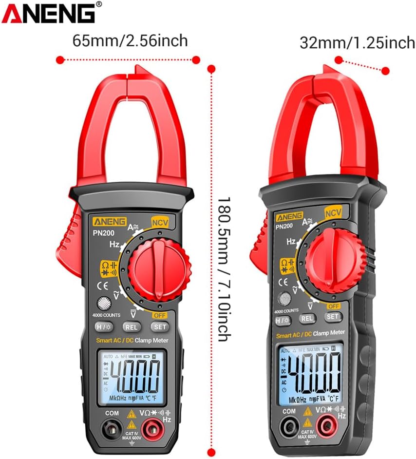
Figure 9.1: The image shows the dimensions of the PN200 clamp meter: approximately 180.5mm (7.10 inches) in height, 65mm (2.56 inches) in width at the clamp, and 32mm (1.25 inches) in body width.
10. Warranty and Support
For warranty information or technical support, please refer to the warranty card included with your product or contact GOLDEN BLUE customer service through the retailer where the product was purchased. Please retain your proof of purchase for warranty claims.


