
1. Introduction
This manual provides comprehensive instructions for the Aitoserlea Double Axis Sun Tracking Controller. This system is designed to automatically orient solar panels towards the sun, maximizing energy capture. It features both automatic and manual operation modes, along with anti-vibration capabilities and low power consumption.
2. Key Features
- Biaxial or uniaxial tracking control.
- Patented pyramid four-quadrant light sensor design.
- Microcontroller (MCU) based signal analysis for precise tracking.
- Relay-controlled motor platform for sun tracking.
- Automatic return to east at night.
- Manual operation mode.
- Jitter function (anti-vibration).
- Pre-calibrated for high precision, no complex parameter settings required.
- Tracking frequency: 1 minute and 20 seconds.
- Low power consumption.
- Anti-vibration design.
3. Main Components
The Aitoserlea Double Axis Sun Tracking Controller system consists of the main controller unit and a light sensor.
3.1. Main Controller
The main controller unit is housed in an IP65 waterproof box. It features an aviation plug for connections and terminal wiring. Installation hole dimensions are approximately 135mm (length), 52mm (width), with 7mm aperture holes.
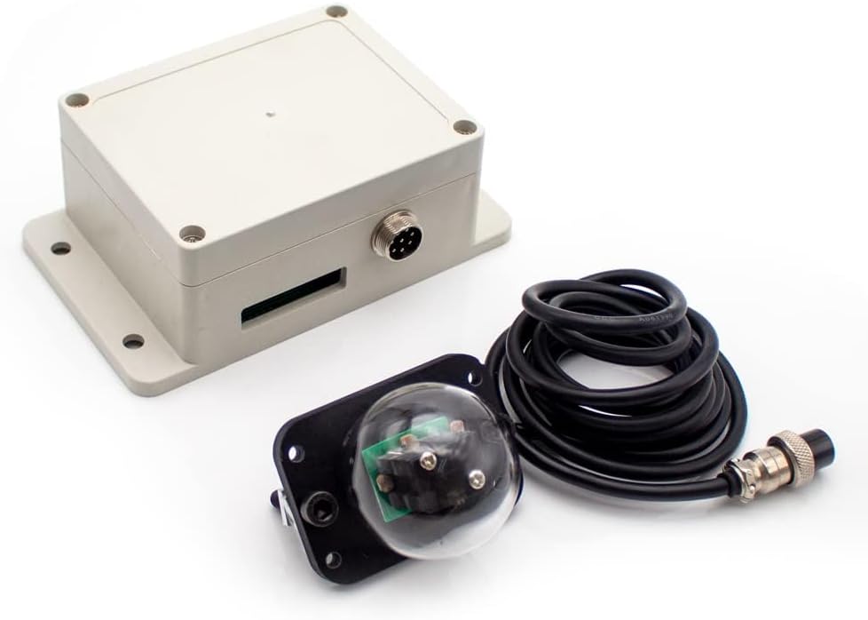
Figure 1: Main Controller, Light Sensor, and Cable
Description: This image displays the complete set of Aitoserlea Double Axis Sun Tracking Controller components, including the main controller unit (a beige rectangular box), the spherical light sensor with its mounting bracket, and the connecting cable with an aviation plug.

Figure 2: Main Controller Dimensions
Description: This image shows the physical dimensions of the main controller unit, indicating a length of 115mm, a width of 90mm, and a height of 55mm.

Figure 3: Controller Terminal Blocks
Description: A view of the bottom side of the controller unit, revealing three green terminal blocks used for connecting various wires.
3.2. Light Sensor
The light sensor utilizes a patented pyramid four-quadrant structure to detect sunlight direction. It connects to the main controller via a cable and aviation plug. Equipped with a glass cover for rain and dust protection, designed for long-term durability (up to 20 years). The default cable length is 2 meters.

Figure 4: Light Sensor Dimensions
Description: This image illustrates the dimensions of the light sensor, showing a diameter of 70mm for the spherical part and a base width of 65mm.
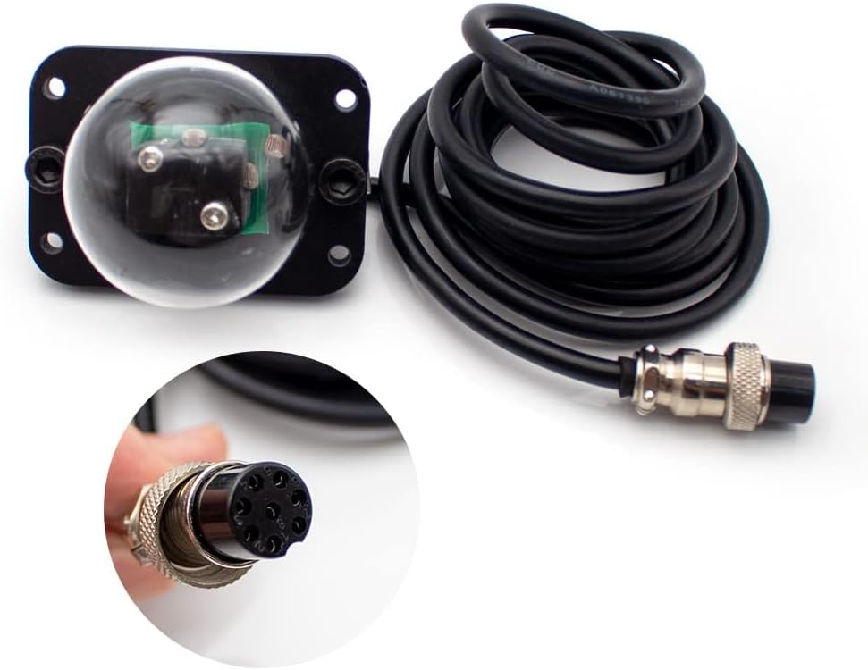
Figure 5: Light Sensor and Cable
Description: A close-up view of the light sensor unit, its attached cable, and the aviation plug used for connecting to the main controller.
3.3. Internal Circuit Board
The internal circuit board contains key components for operation. Refer to the diagram below for component identification:

Figure 6: Internal Circuit Board Components
Description: An overhead view of the controller's internal circuit board, with various components clearly numbered for identification.
- Relay 10A
- Pitching motor connection
- Horizontal motor connection
- Power supply 12-24V input
- Button (likely for mode selection/manual control)
- Single chip microcomputer (MCU)
- Regional switching
- Aviation plug connection
- Manual switching button
- Sunshine detection (light sensor input)
- West limit switch input
- East limit switch input
- North limit switch input
- South limit switch input
- Indicator light
4. Setup and Installation
Careful installation is crucial for optimal performance. Follow these guidelines:
- Refer to the installation diagram for proper wiring and sensor placement.
- Ensure the power supply is DC 12-24V. Do not connect to AC power.
- If a motor turns in the opposite direction to what is desired, reverse its red and black wiring.
- Remove any original wires and connect the normally closed limit switch as indicated.
- The light control probe's installation direction should be parallel to the photovoltaic panel. The arrow on the probe should be inclined upwards, and the installation position should be the highest point of the bracket to ensure an unobstructed view of the sun.

Figure 7: Installation Course Diagram
Description: A detailed diagram showing the wiring connections for the pitch motor, horizontal motor, DC 12-24V power supply, and the light control probe. It also illustrates the correct orientation of the light control probe relative to a solar panel.

Figure 8: Controller Connected to Power Supply
Description: This image shows the main controller unit connected to an external DC power supply, illustrating a typical operational setup.
5. Operating Instructions
The controller operates in two main modes: automatic and manual.
5.1. Automatic Mode (0)
In automatic mode, the system tracks the sun automatically, making adjustments every 1 minute and 20 seconds. At night, the system will automatically return to an east-facing position, preparing for the next sunrise.
5.2. Manual Mode (1)
In manual mode, the four buttons located on the circuit board (labeled 5 and 9 in Figure 6) can be used to control the motor movement directly. Typically, '0' indicates counter-clockwise movement, and '1' indicates clockwise movement for making precise adjustments to the panel's orientation.
Use the manual switching button (labeled 9 on the circuit board diagram, Figure 6) to toggle between automatic and manual modes.
6. Maintenance
To ensure the longevity and optimal performance of your sun tracking controller, regular maintenance is recommended:
- Wiring Inspection: Regularly inspect all wiring connections for security and corrosion. Ensure all plugs are firmly seated.
- Light Sensor Cleaning: Keep the light sensor's glass cover clean to ensure accurate sun detection. Use a soft, damp cloth and mild cleaner if necessary. Avoid abrasive materials that could scratch the glass.
- Physical Stability Check: Periodically check the physical mounting of the controller and motors to ensure they remain stable and securely fastened.
7. Troubleshooting
If you encounter issues with your sun tracking controller, refer to the following troubleshooting steps:
- System not tracking:
- Verify the power supply (DC 12-24V) is connected and providing power.
- Check all wiring connections for looseness or damage.
- Inspect the light sensor for any obstructions, dirt, or damage.
- Ensure the controller is set to automatic mode.
- Motor moving in wrong direction:
- If a motor turns opposite to the desired direction, reverse the red and black wires for that specific motor.
- No movement in manual mode:
- Confirm the controller is switched to manual mode.
- Check the functionality of the manual control buttons.
- Verify motor connections.
- Inaccurate tracking:
- Ensure the light sensor is clean and free from obstructions.
- Verify the light sensor is correctly oriented (arrow inclined upwards, positioned at the highest point on the bracket, and parallel to the solar panel).
8. Specifications
| Feature | Specification |
|---|---|
| Product Dimensions (Main Controller) | 4.5 x 3.5 x 2 inches (115mm x 90mm x 55mm) |
| Item Weight | 1 pound |
| Model Number | ST23092101 |
| Power Supply | DC 12-24V |
| Tracking Frequency | 1 minute 20 seconds |
| Waterproof Rating (Main Controller) | IP65 |
| Light Sensor Cable Length | 2 meters (default) |
| Material (Controller Housing) | Shell |
9. Warranty and Support
Warranty information for this product is not explicitly provided in the available documentation. Please contact your retailer or the manufacturer, Aitoserlea, for details regarding warranty coverage and technical support.