
Vikye Vikyen0gesk7w4b
Vikye ATX B75 HM LGA 1155 Motherboard User Manual
Model: Vikyen0gesk7w4b
1. Introduction
This manual provides detailed instructions for the installation, operation, and maintenance of your Vikye ATX B75 HM LGA 1155 Motherboard. Please read this manual thoroughly before proceeding with installation to ensure proper setup and optimal performance.

Figure 1.1: Vikye ATX B75 HM LGA 1155 Motherboard and included accessories.
This image displays the Vikye ATX B75 HM LGA 1155 Motherboard, showcasing its layout, various ports, and slots. Alongside the motherboard, the image also includes the I/O shield and a SATA data cable, which are typically part of the standard package contents.
2. Key Features
- ATX Structure: Designed with an ATX form factor, this desktop motherboard supports LGA1155 socket processors, including for Core i7, for Core i5, for Core i2, and for E3/V1/V2 series.
- SATA M.2 Interface: Features a SATA M.2 (NGFF M.2) interface that supports AHCI protocol, offering data transfer speeds up to 6Gbps. This interface is an ideal solution for high-speed 2.5-inch SSDs.
- HD VGA Output: Equipped with VGA, DVI, and HD Multimedia Interface (HDMI) outputs, providing versatile display connectivity and supporting digital high-definition video output for a superior visual experience.
- Multi-Phase Power Design: Utilizes a 3+1 phase power design to ensure stable and reliable power delivery to components. All solid-state capacitors contribute to adequate and consistent power supply.
- Durable Construction: Constructed with a 4-layer printed circuit board (PCB), enhancing running speed and providing a more robust and durable structure, reducing the risk of damage.

Figure 2.1: Overview of the Desktop Motherboard, emphasizing its ATX structure and LGA1155 socket compatibility.
This image provides a general view of the motherboard, highlighting its ATX form factor and the central LGA1155 CPU socket, which is compatible with various Intel Core and Xeon E3 series processors.
3. Specifications
| Specification | Detail |
|---|---|
| Board Type | ATX |
| Motherboard Size | Approx. 223.5 x 195mm (8.8 x 7.7 inches) |
| CPU Slot Type | LGA1155 (for E3 V1/V2) |
| Number Of Memory Slots | 4 x DDR3 |
| Maximum Memory Capacity | 64GB |
| Graphics Card Slot | Supports Expansion Of PCIe X16 Graphics Card |
| Network Card | Gigabit Network Card |
| Hard Disk Ports | SATA 3.0 x 1, SATA 2.0 x 1, SATA M.2 (NGFF M.2) |
| Power Supply | 24PIN + ATX 4PIN |
| USB Interface | 2 x USB3.0 (rear), 4 x USB2.0 (rear), USB 3.0 Pin x 1 (front), USB 2.0 Pin x 1 (front) |
| Video Output | VGA, DVI, HD Multimedia Interface (HDMI) |
| Inbuilt Battery | CR2032 x 1 (240mAh) |
| Item Weight | 1.65 pounds |
| Package Dimensions | 12.91 x 9.57 x 2.72 inches |
4. Package Contents
The following items are included in your product package:
- 1 x Vikye ATX B75 HM LGA 1155 Desktop Motherboard
- 1 x Metal I/O Shield
- 1 x Connecting Wire (SATA data cable)
5. Setup and Installation
Before beginning installation, ensure your system is powered off and disconnected from the power source. Handle the motherboard by its edges to avoid static discharge.
5.1. Component Identification
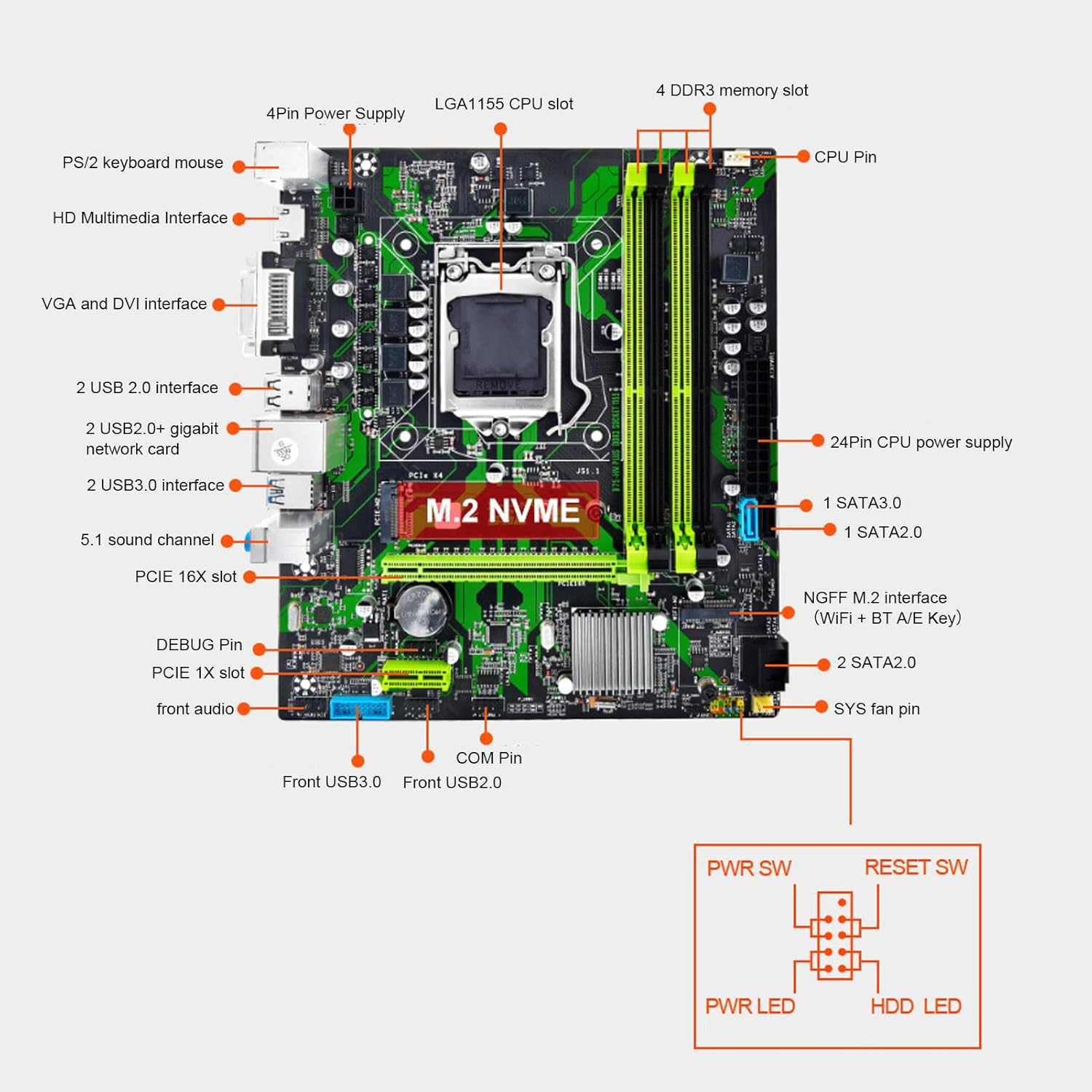
Figure 5.1: Detailed diagram illustrating the various components and ports on the motherboard.
This diagram labels key areas of the motherboard, including the CPU socket, DDR3 memory slots, PCIe slots, SATA ports, M.2 NVMe slot, USB headers, power connectors, and rear I/O panel ports. Refer to this diagram for precise component location during installation.
5.2. CPU Installation
- Locate the LGA1155 CPU socket on the motherboard.
- Gently push down the load lever and pull it away from the socket to open the CPU retention frame.
- Carefully align the CPU with the socket, matching the golden triangle on the CPU with the triangle mark on the socket. Do not force the CPU into place.
- Lower the CPU into the socket.
- Close the retention frame and push the load lever back into its locked position.

Figure 5.2: Close-up view of the LGA1155 CPU socket and the four DDR3 memory slots.
This image provides a detailed look at the CPU socket, showing the retention mechanism, and the adjacent DDR3 memory slots, which are crucial for RAM installation.
5.3. RAM (Memory) Installation
- Open the clips at both ends of the DDR3 memory slots.
- Align the notch on the RAM module with the key in the memory slot.
- Insert the RAM module firmly into the slot until the clips snap into place. Ensure both clips are fully closed.
5.4. Storage Device Installation
5.4.1. M.2 NVMe SSD Installation
- Locate the M.2 NVMe PCIe X4 slot on the motherboard.
- Remove the screw and standoff from the M.2 slot.
- Insert the M.2 SSD into the slot at a 30-degree angle.
- Gently push down the SSD and secure it with the screw onto the standoff.
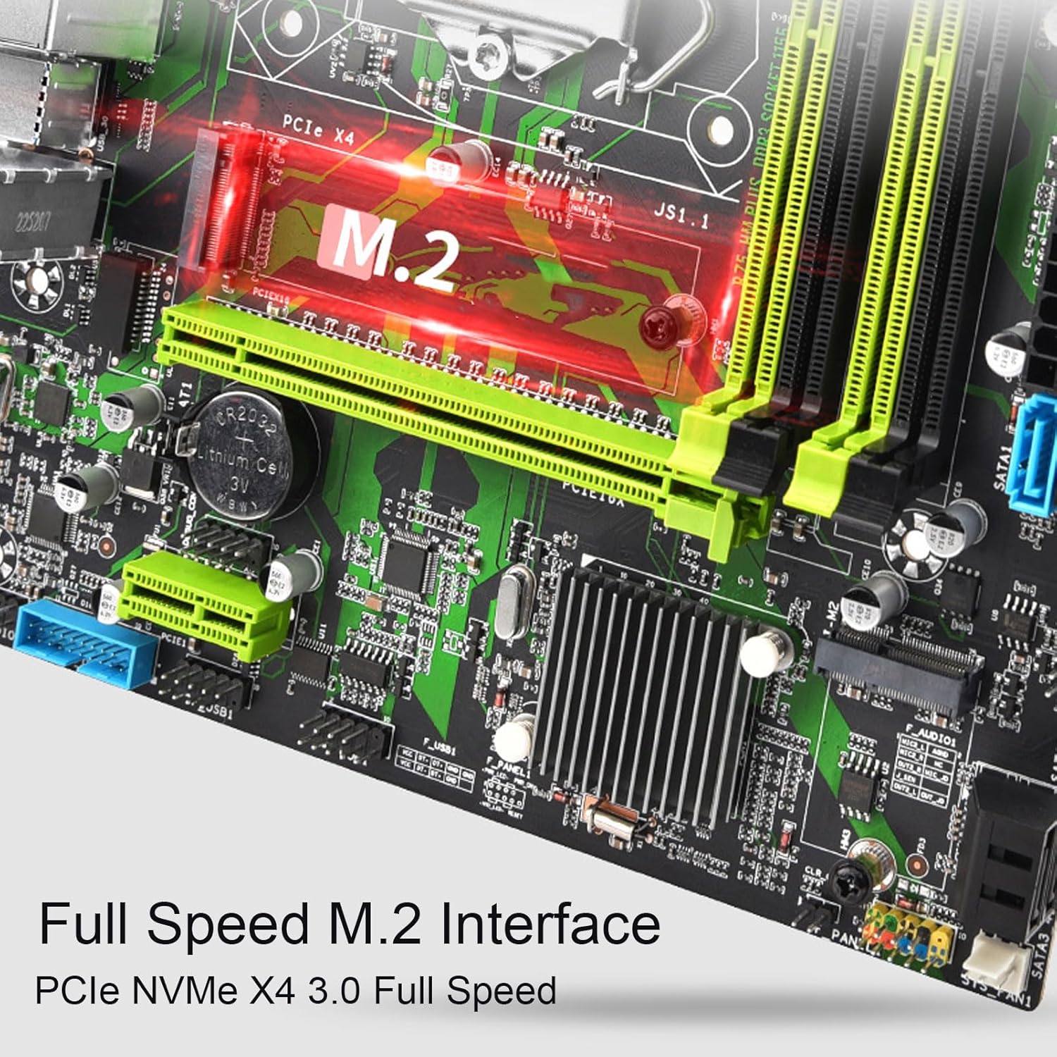
Figure 5.3: Close-up view of the M.2 NVMe PCIe X4 slot, indicating its position on the motherboard.
This image focuses on the M.2 slot, which supports high-speed NVMe SSDs, demonstrating where the drive should be inserted and secured.
5.4.2. SATA Drive Installation
- Connect one end of the SATA data cable (included) to a SATA port on the motherboard (SATA 3.0 or SATA 2.0).
- Connect the other end of the SATA data cable to your SATA hard drive or SSD.
- Connect a SATA power cable from your power supply unit (PSU) to the SATA drive.
5.5. Graphics Card Installation (Optional)
- Locate the PCIe X16 slot.
- Remove the corresponding expansion slot cover from your PC case.
- Align your graphics card with the PCIe X16 slot and press down firmly until it is fully seated and the retention clip locks.
- Secure the graphics card to the case with a screw.
5.6. Power Supply Connections
- Connect the 24-pin ATX power connector from your PSU to the 24-pin power socket on the motherboard.
- Connect the 4-pin ATX 12V power connector from your PSU to the 4-pin power socket near the CPU.
5.7. Front Panel and USB Connections
Connect the cables from your PC case's front panel (Power SW, Reset SW, HDD LED, Power LED) to the corresponding pins on the motherboard's front panel header. Refer to the motherboard diagram (Figure 5.1) for pin assignments.

Figure 5.4: Close-up view of the Front USB 3.0 Interface header.
This image highlights the blue 19-pin header for the front USB 3.0 ports, which provides high-speed connectivity for compatible devices.
Connect your case's front USB 3.0 cable to the USB 3.0 pin header and front USB 2.0 cables to the USB 2.0 pin header.
Connect the front audio cable to the audio header (F_AUDIO).
5.8. Rear I/O Connections
After installing the motherboard into the case, connect your peripherals to the rear I/O ports:
- USB Ports: Connect keyboard, mouse, and other USB devices.
- LAN Port: Connect an Ethernet cable for network access.
- Audio Jacks: Connect speakers, headphones, or microphones.
- Video Outputs (VGA, DVI, HDMI): Connect your monitor.

Figure 5.5: Close-up view of the motherboard's rear I/O panel, showing various connectivity options.
This image details the rear panel ports, including USB 2.0, USB 3.0, Gigabit Ethernet, and audio jacks, which are used for connecting external peripherals and network cables.

Figure 5.6: Close-up view of the HD Multimedia Interface (HDMI), VGA, and DVI video output ports.
This image highlights the integrated video output options available on the motherboard, allowing connection to various display types.
6. Operating Instructions
6.1. First Boot
After all components are installed and connected, ensure all power cables are securely attached. Connect your monitor, keyboard, and mouse. Power on your system. The system should boot to the BIOS/UEFI or begin the operating system installation process if a bootable drive is detected.
6.2. BIOS/UEFI Access
To enter the BIOS/UEFI setup utility, press the DEL key repeatedly during the initial boot sequence (POST). This will allow you to configure system settings, boot order, and other advanced options.
6.3. Driver Installation
After installing your operating system, install the necessary drivers for the motherboard's components (chipset, LAN, audio, etc.). These drivers are typically provided on a CD/DVD included with the motherboard or can be downloaded from the manufacturer's website.
7. Maintenance
Proper maintenance can extend the lifespan of your motherboard and ensure stable operation.
- Dust Removal: Regularly clean dust from the motherboard and other components using compressed air. Ensure the system is powered off and unplugged before cleaning.
- Temperature Monitoring: Monitor system temperatures to prevent overheating, which can lead to instability or damage. Ensure adequate airflow within your PC case.
- BIOS Updates: Periodically check the manufacturer's website for BIOS/UEFI updates. Updates can improve compatibility, stability, and performance. Follow the update instructions carefully to avoid damaging the motherboard.
- Cable Management: Ensure internal cables are neatly routed to improve airflow and prevent interference.
8. Troubleshooting
This section addresses common issues you might encounter.
8.1. No Power / System Not Turning On
- Verify that the 24-pin and 4-pin ATX power connectors are securely plugged into the motherboard.
- Ensure the power supply unit (PSU) is switched on and connected to a working power outlet.
- Check the front panel power switch connection to the motherboard.
- Test the PSU with another system or a PSU tester if available.
8.2. No Display Output
- Ensure your monitor is connected to the correct video output port (VGA, DVI, or HDMI) on the motherboard or dedicated graphics card.
- Verify that the graphics card (if installed) is properly seated in its PCIe slot and has any necessary auxiliary power cables connected.
- Try reseating the RAM modules. Faulty or improperly seated RAM can prevent display output.
- If using integrated graphics, ensure your CPU supports integrated graphics.
8.3. System Instability / Crashes
- Check for overheating. Ensure CPU cooler is properly installed and fans are working.
- Run memory diagnostic tools to check for faulty RAM.
- Ensure all drivers are correctly installed and up to date.
- Check for loose connections of power cables or data cables.
8.4. Storage Device Not Detected
- For SATA drives, ensure both the SATA data cable and power cable are securely connected. Try a different SATA port or cable.
- For M.2 SSDs, ensure it is properly seated and secured in the M.2 slot. Check BIOS settings to ensure the M.2 slot is enabled and configured correctly (e.g., NVMe mode).
- Verify that the drive is recognized in the BIOS/UEFI.
9. Warranty and Support
For warranty information and technical support, please refer to the documentation provided with your purchase or contact Vikye customer service directly. Keep your proof of purchase for warranty claims.
For the latest drivers, BIOS updates, and additional support resources, please visit the official Vikye website.
Ask a question about this manual
Ask about setup, troubleshooting, compatibility, parts, safety, or missing instructions. Manuals+ will review the question and use this page’s manual context to help answer it.