
BAYDE 1794-IA16
User Manual for BAYDE 1794-IA16 SER A Flex I/O 120VAC Input Module
Model: 1794-IA16 | Brand: BAYDE
1. Introduction
This manual provides essential information for the installation, operation, and maintenance of the BAYDE 1794-IA16 SER A Flex I/O 120VAC Input Module. This module is designed for industrial control applications, providing reliable 120VAC input capabilities within a Flex I/O system. Please read this manual thoroughly before attempting to install or operate the module.
2. Safety Information
Always observe the following safety precautions to prevent personal injury and damage to the equipment:
- Ensure all power is disconnected before installing, wiring, or removing the module.
- Only qualified personnel should perform installation and maintenance procedures.
- Adhere to all local and national electrical codes.
- Do not operate the module in environments exceeding its specified temperature and humidity ratings.
- Important: The orange protective wrapper must be removed prior to power-up to ensure proper ventilation and operation.
3. Product Overview
The 1794-IA16 is a 16-point, 120VAC digital input module for the Allen-Bradley Flex I/O system. It provides an interface for sensing 120VAC discrete input signals from field devices.
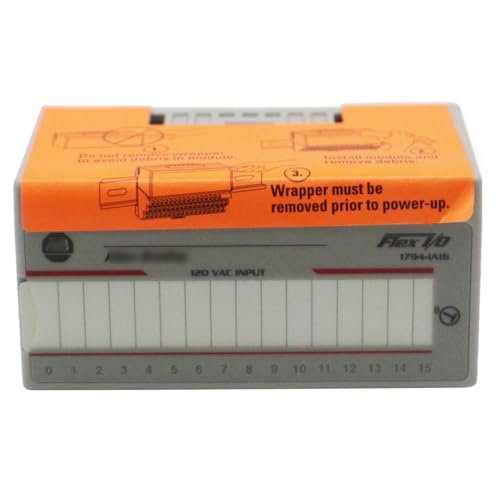
Figure 3.1: Front View of 1794-IA16 Module
This image shows the front of the 1794-IA16 module, highlighting the 120 VAC INPUT label and the 16 input channels (0-15). An orange protective wrapper is visible on the top surface, with instructions regarding its removal before power-up.
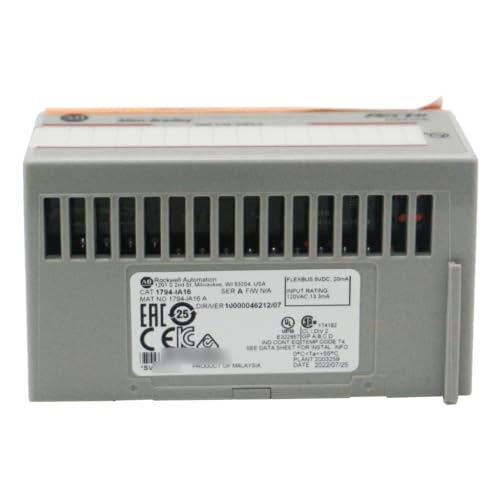
Figure 3.2: Rear View of 1794-IA16 Module
This image displays the rear of the module, featuring ventilation slots and various product labels. These labels include manufacturing details, certifications (CE, EAC), and input rating information (120VAC, 13mA).

Figure 3.3: Top View of 1794-IA16 Module
The top view shows the module's connection interface and the orange protective wrapper. The wrapper explicitly states: "1. Do not remove wrapper to avoid debris in module. 2. Install module and remove debris. 3. Wrapper must be removed prior to power-up."
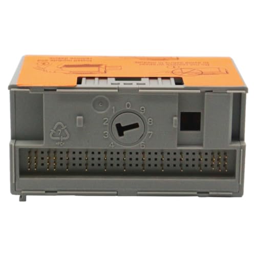
Figure 3.4: Bottom View of 1794-IA16 Module
This image illustrates the bottom of the module, revealing the multi-pin connector interface designed for secure attachment to the Flex I/O terminal base. A keying mechanism is also visible.
4. Setup and Installation
Follow these steps for proper installation of the 1794-IA16 module into a Flex I/O system:
- Power Off: Ensure all power to the Flex I/O system and associated equipment is disconnected.
- Mount Terminal Base: Mount the appropriate Flex I/O terminal base (e.g., 1794-TB3G) to the DIN rail.
- Install Module: Align the 1794-IA16 module with the terminal base. Do not remove the orange protective wrapper yet. The wrapper is designed to prevent debris from entering the module during installation.
- Secure Module: Press the module firmly onto the terminal base until it clicks into place.
- Remove Wrapper: Once the module is securely installed, carefully remove the orange protective wrapper. This wrapper must be removed before applying power to the system.
- Wiring: Connect the 120VAC input signals to the appropriate terminals on the terminal base according to your system's wiring diagram. Refer to the terminal base documentation for specific wiring details.
- Verify Connections: Double-check all wiring for correctness and security.
- Apply Power: Once all connections are verified and the wrapper is removed, power can be applied to the Flex I/O system.
5. Operating Instructions
The 1794-IA16 module operates as part of a larger Flex I/O system controlled by a programmable logic controller (PLC). Its primary function is to convert 120VAC input signals from field devices into digital signals that the PLC can interpret.
- Input Status Indicators: The module typically features LED indicators for each input channel (0-15). A lit LED indicates that the corresponding input is active (receiving a 120VAC signal).
- PLC Programming: The input data from this module will be accessible within the PLC's memory map. Refer to your PLC programming software and documentation for details on how to read and utilize these input points in your control logic.
- System Integration: Ensure the module is properly configured within the Flex I/O adapter's settings (e.g., 1794-AENT, 1794-ASB) to ensure correct communication with the PLC.
6. Maintenance
The 1794-IA16 module is designed for robust industrial use and requires minimal maintenance. However, periodic checks can help ensure long-term reliability:
- Visual Inspection: Periodically inspect the module and its wiring for any signs of damage, loose connections, or excessive dust accumulation.
- Cleaning: If necessary, gently clean the module's exterior with a soft, dry cloth. Do not use solvents or abrasive cleaners. Ensure power is off before cleaning.
- Environmental Control: Maintain the operating environment within specified temperature and humidity ranges to prevent premature component failure.
7. Troubleshooting
This section provides guidance for common issues. For more complex problems, consult a qualified technician or contact support.
| Problem | Possible Cause | Solution |
|---|---|---|
| Module not recognized by PLC. | Incorrect configuration in PLC program; Loose connection to terminal base or adapter; Module not fully seated. | Verify PLC I/O configuration; Check all connections; Ensure module is securely latched onto the terminal base. |
| Input LED not illuminating when signal is present. | No 120VAC signal at input; Faulty wiring; Damaged input channel. | Verify 120VAC signal with a multimeter; Check wiring continuity; If other inputs work, the channel may be faulty (replace module if necessary). |
| Module appears dead (no power/status LEDs). | No power to Flex I/O system; Module not receiving power from terminal base; Orange protective wrapper still present. | Check system power supply; Ensure terminal base is powered; Verify orange wrapper is removed. |
8. Specifications
Key technical specifications for the 1794-IA16 SER A Flex I/O 120VAC Input Module:
| Attribute | Value |
|---|---|
| Model Number | 1794-IA16 |
| Brand | BAYDE |
| Module Type | Flex I/O 120VAC Input Module |
| Number of Inputs | 16 |
| Input Voltage | 120VAC |
| Maximum Supply Voltage | 120 Volts |
| Current Draw | 13mA (from product image) |
| ASIN | B0CHW2RVLK |
| UPC | 614160208208 |
| Manufacturer | BAYDE |
| Country of Origin | China |
| Date First Available | May 6, 2023 |
9. Warranty and Support
BAYDE products are manufactured to high-quality standards. For specific warranty details, please refer to the documentation provided with your purchase or contact the seller directly.
For technical support or inquiries regarding other model requirements, please consult the seller, Yunteng Industry, or the manufacturer, BAYDE. The seller can be reached via their Amazon storefront: Yunteng Industry Seller Page.
Quality assurance: All of our products are original new, produced by the brand original factory.
Ask a question about this manual
Ask about setup, troubleshooting, compatibility, parts, safety, or missing instructions. Manuals+ will review the question and use this page’s manual context to help answer it.