1. Introduction
The NOYAFA NF-8509 is a versatile instrument designed for network and electrical professionals. It integrates the functionalities of a network cable tester and a digital multimeter, offering comprehensive testing capabilities for various applications. This device is suitable for engineering wiring, network maintenance, and general electrical measurements.

Figure 1: NOYAFA NF-8509 Main Unit and Receiver with Test Leads.
2. Safety Information
Please read and understand all safety warnings and operating instructions before using this instrument. Failure to follow these instructions may result in electric shock, fire, or serious injury.
- Do not use the device if it appears damaged or is operating abnormally.
- Ensure correct function selection and terminal connection before measurement.
- Avoid contact with live circuits when connecting test leads.
- Do not exceed the maximum input values specified for each function.
- Use caution when working with voltages above 30V AC RMS, 42V peak, or 60V DC, as these pose a shock hazard.
- Only use the provided or recommended accessories and replacement parts.
- The device is designed for indoor use and should be kept away from moisture and extreme temperatures.
- When charging the main unit, use a slow 2A USB A to USB C charger to prevent potential battery damage.
3. Package Contents
Verify that all items are present and undamaged upon opening the package:
- 1x NF-8509 Transmitter (Main Unit)
- 1x NF-8509 Receiver (Wire Tracker)
- 1x User Manual
- 1x Product Box
- 1x Pair of Test Leads (for Multimeter functions)
- 1x USB Type-C Charging Cable
- 1x 9V Battery (for Receiver, may be pre-installed)
- 1x Pair of Headphones (for wire tracing)
- 1x RJ45 to Alligator Clip Cable (for network testing)
4. Product Components and Overview
Familiarize yourself with the main components of the NF-8509 Transmitter and Receiver.
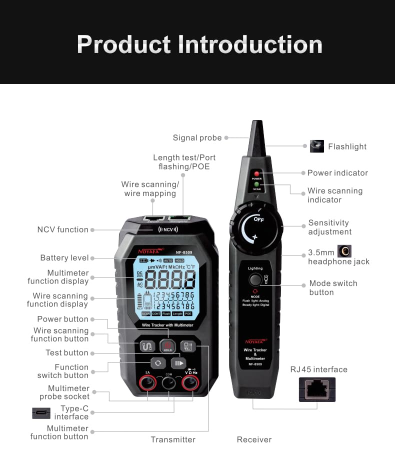
Figure 2: Detailed diagram of the NF-8509 Transmitter and Receiver components, including buttons, ports, and display elements.
Transmitter (Main Unit) Features:
- LCD Display: Shows measurement results, battery level, and selected functions.
- Function Buttons: For selecting network testing modes (SCAN, CONT, FLASH, LENGTH, POE) and multimeter functions.
- Multimeter Probe Sockets: For connecting test leads for electrical measurements.
- RJ45 Ports: For connecting network cables.
- Type-C Interface: For charging the internal battery.
- NCV Function: Non-contact voltage detection.
Receiver (Wire Tracker) Features:
- Signal Probe: For tracing cables.
- Power Indicator: LED to show power status.
- Sensitivity Adjustment: Rotary knob to adjust tracing sensitivity.
- Lighting: Built-in LED flashlight.
- Mode Switch Button: To select tracing modes (Flash, Analog, Digital).
- 3.5mm Headphone Jack: For connecting headphones during tracing.
- RJ45 Interface: For direct connection to network cables.
5. Setup
5.1 Charging the Transmitter
The main unit (transmitter) has a built-in rechargeable lithium battery. Connect the provided USB Type-C charging cable to the Type-C interface on the transmitter and a standard USB-A power adapter (5V/2A recommended). The battery indicator on the display will show charging status. Avoid using fast USB-C chargers to prevent potential battery damage.

Figure 3: The main unit (transmitter) features a USB Type-C charging port for its internal 1500mAh rechargeable battery.
5.2 Installing Battery in Receiver
The receiver (wire tracker) requires a 9V battery. Open the battery compartment on the back of the receiver, insert the 9V battery with correct polarity, and close the compartment securely.
5.3 Initial Power On
Press and hold the power button on both the transmitter and receiver to turn them on. The LCD display on the transmitter will illuminate.
6. Operating Instructions
6.1 Network Cable Testing Functions
Connect the network cable to be tested to the appropriate RJ45 port on the transmitter. For most network tests, the remote end of the cable should be connected to the receiver's RJ45 port or left unterminated depending on the test.
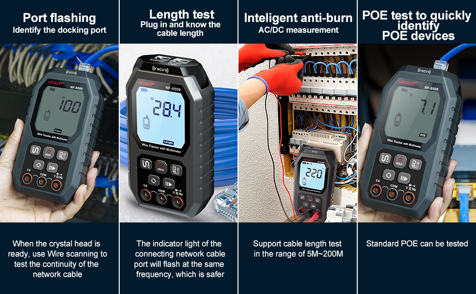
Figure 4: Overview of network cable testing capabilities including Port Flashing, Length Test, Anti-Burn protection, and POE Test.
6.1.1 Continuity and Wire Mapping (CONT)
Connect one end of the RJ45 cable to the transmitter's "SCAN/CONT/FLASH/LENGTH/POE" port and the other end to the receiver's RJ45 port. Select the "CONT" mode on the transmitter. The display will show the wiring sequence and identify any open circuits, shorts, or cross-overs.
6.1.2 Cable Length Measurement (LENGTH)
Connect one end of the network cable to the transmitter's "SCAN/CONT/FLASH/LENGTH/POE" port. The other end of the cable should be open (not connected to anything). Select the "LENGTH" mode. The device uses Time Domain Reflectometry (TDR) to measure the cable length and can also detect the distance to a fault. The measurement range is typically 5m to 200m.

Figure 5: The NF-8509 performing a cable length test and demonstrating the port flashing function.

Figure 6: The device utilizes Time Domain Reflectometry (TDR) technology for accurate cable length measurement and fault location.
6.1.3 Port Flashing (FLASH)
Connect the network cable to the transmitter's "SCAN/CONT/FLASH/LENGTH/POE" port and the other end to a network switch or router. Select the "FLASH" mode. The corresponding port LED on the connected switch will flash at a specific frequency (around 3 seconds), allowing for quick identification of the target port among many.
6.1.4 POE Testing
Connect the network cable from a PoE source to the transmitter's "SCAN/CONT/FLASH/LENGTH/POE" port. Select the "POE" mode. The device will quickly identify PoE device information, including PoE voltage, power supply polarity, power supply mode, and the type of PSE (af or at standard). It automatically detects and switches between 10M/100M/1000M modes.
6.1.5 Wire Tracing (SCAN)
Connect the network cable to the transmitter's "SCAN/CONT/FLASH/LENGTH/POE" port. Turn on the receiver and select the desired tracing mode (Analog or Digital). Move the receiver's signal probe along the cable path. The receiver will emit an audible tone, which increases in volume as it gets closer to the cable. Use headphones for clearer detection in noisy environments.

Figure 7: The receiver being used to trace a network cable, illustrating its wire scanning capability.
6.2 Multimeter Functions
Connect the test leads to the appropriate multimeter probe sockets (SA and COM) on the transmitter. Select the desired multimeter function using the function switch button.

Figure 8: Display of various multimeter functions including AC/DC voltage, diode, buzzer, resistance, and ambient temperature measurement.
6.2.1 AC/DC Voltage Measurement
Connect the test leads in parallel to the circuit to measure voltage. The device automatically recognizes AC or DC voltage.
6.2.2 Resistance Measurement
Ensure the circuit is de-energized before measuring resistance. Connect the test leads across the component. The device automatically recognizes the resistance value.
6.2.3 Continuity Test
For continuity, connect the test leads across the circuit or component. A buzzer will sound if continuity is detected (low resistance).
6.2.4 Diode Test
Connect the test leads across the diode. The display will show the forward voltage drop of the diode.
6.2.5 NCV (Non-Contact Voltage) Detection
Hold the transmitter near an AC signal source. The device will emit an alarm and display an NCV indicator if AC voltage is detected without direct contact, enhancing safety.

Figure 9: The NCV function allows for safe, non-contact detection of AC voltage, indicated by an alarm and display icon.
6.2.6 Temperature Measurement
The device can measure ambient temperature. The display shows the temperature in Celsius. (Note: The unit may not offer Fahrenheit conversion).
6.3 Additional Features
6.3.1 LED Flashlight
The receiver includes an LED flashlight for working in dimly lit environments. Activate it using the dedicated button on the receiver.

Figure 10: The receiver's integrated LED light assists in working in dark conditions.
7. Maintenance
- Cleaning: Wipe the device with a dry, soft cloth. Do not use abrasive cleaners or solvents.
- Storage: Store the device in a cool, dry place, away from direct sunlight and extreme temperatures. If storing for extended periods, remove the 9V battery from the receiver.
- Battery Care: Recharge the transmitter's battery regularly, even if not in use, to maintain battery health. Avoid overcharging or fully discharging the battery frequently.
- Fuse Replacement: The device features an easily accessible internal fuse. Refer to the product diagram for its location. Replace only with a fuse of the specified type and rating.
8. Troubleshooting
- Device does not power on:
- Check the battery level of the transmitter and recharge if necessary.
- Ensure the 9V battery in the receiver is correctly installed and not depleted.
- Inaccurate cable length measurement:
- Ensure the remote end of the cable is open (not connected to anything) for length measurement.
- Verify the cable type and condition. Damaged cables can lead to inaccurate readings.
- Wire tracing signal is weak or absent:
- Adjust the sensitivity knob on the receiver.
- Ensure the transmitter is correctly connected to the cable.
- Check for strong electromagnetic interference in the environment.
- Verify the receiver's 9V battery.
- Multimeter readings are incorrect:
- Ensure test leads are properly connected to the correct input jacks.
- Verify the correct function is selected for the measurement.
- Check the condition of the test leads for damage.
9. Specifications
| Feature | Specification |
|---|---|
| Model Number | NF-8509 |
| Product Dimensions (Transmitter) | 6 x 2.2 x 2 inches |
| Item Weight | 1.3 Pounds |
| Power Source (Transmitter) | Rechargeable Lithium Metal Battery (included) |
| Power Source (Receiver) | 1x 9V Battery (included) |
| Measurement Type | Multimeter, Voltmeter, Network Cable Tester |
| Cable Length Test Range | 5m - 200m (TDR) |
| POE Test | Voltage, Polarity, Mode, PSE Type (af/at) |
| NCV Detection | Yes |
| Display | HD Backlit LCD |

Figure 11: Dimensions of the NF-8509 Transmitter and Receiver units.
10. Support and Contact Information
For technical assistance, troubleshooting, or warranty inquiries, please contact NOYAFA customer support. Refer to the official NOYAFA website or your purchase documentation for the most current contact details.
NOYAFA is committed to providing reliable products and professional after-sales support.
Official Website: Visit the NOYAFA Store on Amazon


