
1. Product Overview
The YUHANUS K03-P9-DSK is a comprehensive door access control system designed to enhance security and manage entry to your premises. This system integrates multiple access methods including password input, RFID card swiping, and remote control. It features an electric strike lock for secure door locking, an exit button for convenient indoor egress, and a doorbell chime for visitor notification.
Key features include:
- Multiple Access Options: Supports password, RFID card, and remote control for entry.
- Enhanced Security: The 2200LBS Electric Strike Lock provides robust door security.
- Visitor Management: Integrated doorbell and remote unlock feature for convenient visitor access.
- User-Friendly Installation: Designed for straightforward setup.
- Cost-Effective Solution: An efficient system for managing access and preventing unauthorized entry.
2. Package Contents
Verify that all components listed below are included in your package:
- RFID Keypad
- Electric Strike Lock
- Power Supply Control
- Exit Button
- Doorbell Chime
- Remote Controls (2 units)
- RFID Cards/Key Fobs (5 units)
- Mounting Hardware and Cables

Figure 2.1: Complete system kit components.
3. Specifications
| Feature | Specification |
|---|---|
| Brand | YUHANUS |
| Model Number | K03-P9-DSK |
| Power Source | Corded Electric (AC110V-240V input, DC12V output) |
| Connectivity Technology | Wired |
| Control Method | Touch (Keypad), RFID, Remote Control |
| Alert Type | Audio & Motion |
| Item Dimensions (L x W x H) | 11.81 x 7.09 x 3.15 inches |
| Item Weight | 2.61 pounds |
| Batteries | 1 CR2032 battery required (included for remote) |
| UPC | 769894490518 |
4. Safety Information
Please read and understand all safety instructions before installation and operation. Failure to follow these instructions may result in electric shock, fire, or other hazards.
- Electrical Safety: Ensure power is disconnected before performing any wiring or maintenance. All electrical connections should be made by a qualified professional if you are unsure.
- Hazardous Voltage: The power supply unit contains hazardous voltage. Do not open the power supply cover.
- Installation Environment: Install the system in a dry, protected area, away from direct sunlight, rain, or extreme temperatures.
- Cable Management: Route all cables securely to prevent tripping hazards or damage.
5. Installation and Wiring
5.1. Components Overview

Figure 5.1: RFID Keypad

Figure 5.2: Power Supply Control

Figure 5.3: Electric Strike Lock

Figure 5.4: Push to Exit Button

Figure 5.5: Doorbell Chime

Figure 5.6: Remote Control
5.2. Wiring Diagram
Follow the wiring diagram carefully to connect all components of the access control system. Ensure all connections are secure and correctly matched to avoid damage or malfunction.
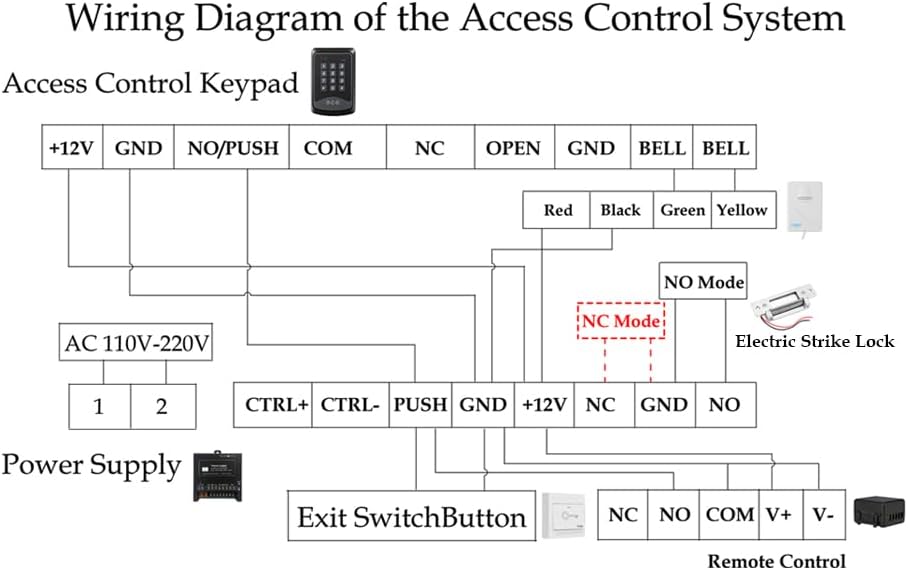
Figure 5.7: Wiring Diagram of the Access Control System
Wiring Notes:
- Connect the Access Control Keypad to the Power Supply using the +12V and GND terminals.
- The Electric Strike Lock can be wired in either NO (Normally Open) or NC (Normally Closed) mode. Refer to section 5.3 for mode adjustment. Connect the lock to the appropriate NO/NC and GND terminals on the Power Supply.
- The Exit Switch Button connects to the PUSH and GND terminals on the Power Supply.
- The Doorbell Chime connects to the BELL terminals on the Keypad.
- The Remote Control Receiver connects to the +12V, GND, NO, and COM terminals on the Power Supply.
- Ensure the AC 110V-220V input is correctly connected to the Power Supply.
5.3. Electric Strike Lock Mode Adjustment (NO/NC)
The electric strike lock supports two operating modes: NO (Normally Open) and NC (Normally Closed). The default mode is typically NO (Fail-Secure), meaning the door is closed when power is off. If you require NC (Fail-Safe) mode, where the door is open when power is off, you can adjust it as follows:

Figure 5.8: Electric Strike Lock NO/NC Mode Adjustment
- Step 1: Unscrew Screw 2.
- Step 2: Loosen Screw 1, then slide it to the other side.
- Step 3: Tighten Screw 1 and Screw 2.
Mode Definitions:
- NO Mode (Normally Open / Fail-Secure): When power is off, the door remains locked. Power is required to unlock.
- NC Mode (Normally Closed / Fail-Safe): When power is off, the door is unlocked. Power is required to lock.
6. Operating Instructions
6.1. Initial Setup
The default Master Code for the RFID Keypad is 9999. It is highly recommended to change this code immediately after installation for security purposes.
6.2. Setting a New PIN
To set a new PIN for unlocking the door:
- Press * 9999 # (where 9999 is the default Master Code or your current Master Code).
- Press 5.
- Enter your New PIN (e.g., 123456).
- Press #.
- Re-enter your New PIN.
- Press * to confirm.
6.3. Enrolling RFID Cards
To enroll new RFID cards for access:
- Press * 9999 # (where 9999 is the Master Code).
- Press 1.
- Swipe each RFID card you wish to enroll across the keypad's card reader. The keypad will beep to confirm enrollment.
- Press * to exit enrollment mode.
6.4. Unlocking Methods
- Using PIN: Enter your programmed PIN on the keypad.
- Using RFID Card: Swipe an enrolled RFID card across the keypad's card reader.
- Using Remote Control: Press the unlock button on the remote control.
- Using Exit Button: Press the 'Push to Exit' button from inside the premises.
6.5. Locking Method
- Using Remote Control: Press the lock button on the remote control.
6.6. Operational Demonstration Video
Video 6.1: This video demonstrates the various functions of the YUHANUS Door Access Control System, including how to unlock the door using the exit button, setting a new PIN, enrolling RFID cards, and using both RFID cards and the remote control for unlocking and locking. It also shows how to change the electric strike lock between NO (Normally Open) and NC (Normally Closed) modes and the operational difference between these modes.
7. Maintenance
Regular maintenance ensures the longevity and optimal performance of your access control system.
- Cleaning: Wipe the keypad and other components with a soft, dry cloth. Avoid abrasive cleaners or solvents.
- Battery Replacement: The remote controls use CR2032 batteries. Replace them when the signal weakens or the remote stops responding.
- Cable Inspection: Periodically check all wiring for signs of wear, damage, or loose connections.
- Lock Mechanism: Ensure the electric strike lock mechanism is free of obstructions and operates smoothly.
8. Troubleshooting
If you encounter issues with your access control system, refer to the following common problems and solutions:
| Problem | Solution |
|---|---|
| System is unresponsive / No power | Check the power supply connection and ensure it is plugged into a working outlet. Verify all wiring to the power supply is correct and secure. |
| Door does not unlock with PIN/Card | Ensure the PIN is entered correctly. For RFID cards, verify the card has been properly enrolled. Check the wiring between the keypad and the electric strike lock. |
| Remote control does not work | Replace the CR2032 battery in the remote control. Ensure the remote control receiver is correctly wired and powered. |
| Electric strike lock makes a continuous buzzing noise | This can indicate an issue with the power supply or the lock itself. Ensure the power supply is providing stable 12V DC. Check the lock's wiring for any shorts or incorrect connections. If the buzzing persists, the lock or power supply may be faulty. |
| Door remains unlocked even when power is off | This indicates the electric strike lock is in NC (Fail-Safe) mode. If you require the door to be locked when power is off, adjust the lock to NO (Fail-Secure) mode as described in Section 5.3. |
9. Warranty and Support
For warranty information or technical support, please refer to the contact details provided with your purchase or visit the YUHANUS official website. Keep your purchase receipt as proof of purchase for warranty claims.