
MESTEK DM96A
MESTEK DM96A Digital Multimeter User Manual
Model: DM96A
1. Product Overview
The MESTEK DM96A is a versatile TRMS 6000 Counts Digital Multimeter designed for accurate measurement of various electrical parameters. It is suitable for both industrial and household electrical troubleshooting.
Key features include:
- Accurate measurement of AC/DC Current, AC/DC Voltage, Capacitance, Resistance, Diode, ON-OFF test, Temperature, and Live Wire Identification.
- Non-Contact Voltage (NCV) testing with audible and visual alarms for enhanced safety.
- Auto-ranging functionality for simplified operation.
- Backlit LCD screen and built-in flashlight for use in dimly lit environments.
- Additional features such as Data Hold, Auto Shut-off, Low Battery Indicator, and MAX Value display.

Figure 1.1: MESTEK DM96A Multimeter and included accessories.

Figure 1.2: Overview of the MESTEK DM96A's multi-functional capabilities.
2. What's in the Box
Upon opening the package, please verify that all the following items are included:
- 1 x MESTEK DM96A Digital Multimeter
- 1 x Temperature Probe (K-Type thermocouple)
- 1 x Pair of Test Leads (Red and Black)
- 2 x AA Batteries (1.5V)
- 1 x Mini Screwdriver
- 1 x User Manual

Figure 2.1: Contents of the MESTEK DM96A package.
3. Safety Information
Please read and understand all safety warnings and operating instructions before using this multimeter. Failure to follow these instructions may result in electric shock, fire, or serious injury.
General Safety Rules:
- Always ensure the multimeter is in good working condition and that the test leads are not damaged before use.
- Do not apply voltage or current that exceeds the maximum rated values for the multimeter. This device is IEC Rated CAT.III 1000V.
- Use extreme caution when working with live circuits. Always assume circuits are live until proven otherwise.
- Wear appropriate personal protective equipment (PPE), such as safety glasses and insulated gloves, when performing electrical measurements.
- Do not use the multimeter if the battery is low, as this may lead to inaccurate readings.
- Ensure the function switch is set to the correct range before making measurements.
- The multimeter features full range over-load protection, anti-burn dual fuse, thermistor protection circuit, and a double insulated unit for enhanced security.

Figure 3.1: Dual fuse protection for enhanced safety.
4. Setup
4.1 Battery Installation
The MESTEK DM96A Multimeter requires 2 AA batteries (included). To install or replace batteries:
- Ensure the multimeter is turned OFF.
- Locate the battery compartment on the back of the multimeter.
- Use the included mini screwdriver to loosen the screw securing the battery cover.
- Remove the battery cover.
- Insert the 2 AA batteries, observing the correct polarity (+ and -) as indicated inside the compartment.
- Replace the battery cover and tighten the screw.
4.2 Connecting Test Leads
To connect the test leads:
- Insert the black test lead into the "COM" (Common) input jack.
- For most measurements (Voltage, Resistance, Capacitance, Diode, Continuity, Temperature), insert the red test lead into the "VΩHz" input jack.
- For current measurements (Amps, Milliamps, Microamps), insert the red test lead into the "10A" or "mA/uA" input jack, depending on the expected current range.

Figure 4.1: Multimeter input jacks and controls.
4.3 Kickstand and Pen Slot
The multimeter features a built-in kickstand for convenient hands-free operation and a back pen slot to store test leads.
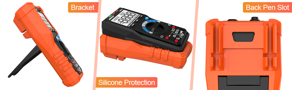
Figure 4.2: Multimeter features: Kickstand, Silicone Protection, and Back Pen Slot.
5. Operating Instructions
The MESTEK DM96A is an auto-ranging multimeter, simplifying operation. Simply switch the dial to the desired function, and the meter will automatically select the appropriate range.

Figure 5.1: Auto-ranging and accurate measurement.
5.1 AC/DC Voltage Measurement
To measure voltage:
- Set the rotary switch to the V~ (AC Voltage) or V- (DC Voltage) position.
- Connect the red test lead to the "VΩHz" jack and the black test lead to the "COM" jack.
- Connect the test probes in parallel to the circuit or component you wish to measure.
- Read the voltage value on the LCD display.

Figure 5.2: Examples of AC/DC Voltage measurement.
Video 5.1: Demonstration of AC and DC Voltage testing using the MESTEK DM96A Multimeter.
5.2 AC/DC Current Measurement
To measure current:
- Set the rotary switch to the A~ (AC Current) or A- (DC Current) position.
- Connect the red test lead to the "10A" or "mA/uA" jack and the black test lead to the "COM" jack.
- Open the circuit and connect the test probes in series with the circuit or component.
- Read the current value on the LCD display.
Figure 5.3: Example of AC/DC Current measurement.
Video 5.2: Demonstration of AC and DC Current testing using the MESTEK DM96A Multimeter.
5.3 Resistance Measurement
To measure resistance:
- Set the rotary switch to the Ω (Resistance) position.
- Connect the red test lead to the "VΩHz" jack and the black test lead to the "COM" jack.
- Connect the test probes across the component to measure its resistance. Ensure the circuit is de-energized before measuring resistance.
- Read the resistance value on the LCD display.
Figure 5.4: Example of Resistance measurement.
Video 5.3: Demonstration of Resistance testing using the MESTEK DM96A Multimeter.
5.4 Capacitance Measurement
To measure capacitance:
- Set the rotary switch to the -||- (Capacitance) position.
- Connect the red test lead to the "VΩHz" jack and the black test lead to the "COM" jack.
- Connect the test probes across the capacitor. Ensure the capacitor is fully discharged before measurement.
- Read the capacitance value on the LCD display.
Figure 5.5: Example of Capacitance measurement.
Video 5.4: Demonstration of Capacitance testing using the MESTEK DM96A Multimeter.
5.5 Diode Test
To perform a diode test:
- Set the rotary switch to the Diode position.
- Connect the red test lead to the "VΩHz" jack and the black test lead to the "COM" jack.
- Connect the red probe to the anode and the black probe to the cathode of the diode.
- Read the forward voltage drop on the LCD display. Reverse the probes to check for an open circuit (OL).
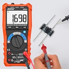
Figure 5.6: Diode test in progress.
Video 5.5: Demonstration of Diode testing using the MESTEK DM96A Multimeter.
5.6 Continuity Test
To check for continuity:
- Set the rotary switch to the Continuity position.
- Connect the red test lead to the "VΩHz" jack and the black test lead to the "COM" jack.
- Connect the test probes across the circuit or component.
- An audible beep indicates continuity (low resistance). "OL" indicates an open circuit.
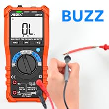
Figure 5.7: Continuity test with audible alert.
Video 5.6: Demonstration of Continuity testing using the MESTEK DM96A Multimeter.
5.7 Temperature Measurement
To measure temperature:
- Set the rotary switch to the °C/°F (Temperature) position.
- Connect the temperature probe to the appropriate input jacks (usually "VΩHz" and "COM").
- Place the tip of the temperature probe on or near the object whose temperature you wish to measure.
- Read the temperature value on the LCD display. Use the SEL button to switch between Celsius and Fahrenheit.

Figure 5.8: Temperature measurement range and examples.
Video 5.7: Demonstration of Temperature measurement using the MESTEK DM96A Multimeter.
5.8 Non-Contact Voltage (NCV) Testing
The NCV function allows for safe detection of AC voltage without direct contact.
- Set the rotary switch to the NCV Live position.
- Place the top end of the multimeter near the conductor or outlet you suspect has AC voltage.
- The multimeter will emit an audible beep and the NCV indicator light will illuminate, with increasing frequency and intensity as it gets closer to a live voltage source.

Figure 5.9: Non-Contact Voltage testing in action.
Video 5.8: Demonstration of Non-Contact Voltage (NCV) testing using the MESTEK DM96A Multimeter.
5.9 Live Wire Identification
To identify live wires:
- Set the rotary switch to the NCV Live position.
- Connect the red test lead to the "VΩHz" jack. The black test lead is not needed for this function.
- Touch the red probe to the wire you want to test.
- If the wire is live, the multimeter will indicate "LIVE" on the display and emit an audible and visual alarm.

Figure 5.10: Live Wire identification.
Video 5.9: Demonstration of Live Wire Identification using the MESTEK DM96A Multimeter.
5.10 Data Hold Function
Press the HOLD button to freeze the current reading on the display. Press it again to release the hold and resume live readings.

Figure 5.11: Data Hold function.
5.11 Backlight and Flashlight
Press the */Light button to turn on the LCD backlight for improved visibility in low-light conditions. Press and hold the button to activate the built-in flashlight.

Figure 5.12: Backlight and Flashlight features.

Figure 5.13: Multimeter flashlight in use in a dark environment.

Figure 5.14: Flashlight for low-light conditions.
Video 5.10: Demonstration of the flashlight and NCV function in a dark environment.
5.12 Auto Shut-off
The multimeter will automatically power off after approximately 20 minutes of inactivity to conserve battery life.
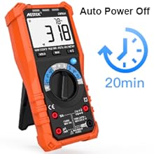
Figure 5.15: Auto Power Off feature.
5.13 Low Battery Indicator
A low battery icon will appear on the display when the battery voltage is low, indicating that the batteries need to be replaced.

Figure 5.16: Low Battery Indicator.
6. Maintenance
6.1 Cleaning
To clean the multimeter, wipe the case with a damp cloth and mild detergent. Do not use abrasives or solvents. Ensure the device is completely dry before storage or next use.
6.2 Battery Replacement
Refer to Section 4.1 for instructions on battery replacement when the low battery indicator appears.
6.3 Fuse Replacement
If the current measurement function stops working, the fuse may need replacement. Refer to the detailed instructions in the full user manual for fuse replacement procedures. Always use fuses of the specified type and rating.
6.4 Storage
When not in use for extended periods, remove the batteries to prevent leakage and store the multimeter in a cool, dry place away from direct sunlight and extreme temperatures.

Figure 6.1: The multimeter is a multifunction tool used in different fields.
7. Troubleshooting
| Problem | Possible Cause | Solution |
|---|---|---|
| Multimeter does not power on. | Dead or incorrectly installed batteries. | Check battery polarity or replace batteries. |
| Inaccurate readings. | Low battery, incorrect function selection, or damaged test leads. | Replace batteries, ensure correct function is selected, inspect and replace test leads if damaged. |
| "OL" (Overload) displayed. | Measurement exceeds the meter's range or an open circuit. | Ensure the measurement is within the meter's specifications. Check for open circuits in continuity/resistance tests. |
| No current measurement. | Blown fuse. | Replace the fuse (refer to full manual for details). |
| NCV function not responding. | No AC voltage present or interference. | Ensure AC voltage is present. Move away from other electrical devices that might cause interference. |
8. Specifications
| Parameter | Value |
|---|---|
| Model Number | DM96A |
| Display | 6000 Counts TRMS Digital Display |
| Sampling Speed | 3 times/second |
| AC/DC Voltage | Yes (Auto-Ranging) |
| AC/DC Current | Yes (Auto-Ranging) |
| Resistance | Yes (Auto-Ranging) |
| Capacitance | Yes (Auto-Ranging) |
| Diode Test | Yes |
| Continuity Test | Yes (with audible alarm) |
| Temperature Measurement | -4°F to 1832°F (-20°C to 1000°C) |
| NCV Function | Yes (Non-Contact Voltage) |
| Live Wire Identification | Yes |
| Power Source | 2 x 1.5V AA Batteries |
| Auto Shut-off | Approx. 20 minutes |
| Dimensions (L x W x H) | 7.2 x 3.4 x 1.9 inches |
| Weight | 1.17 Pounds |
| Safety Rating | IEC Rated CAT.III 1000V, CE |
9. Warranty & Support
MESTEK provides a comprehensive 36-month after-sale service and lifetime technical support for the DM96A Digital Multimeter.
If you encounter any issues or have questions regarding the product, please do not hesitate to contact MESTEK customer support. Our team is dedicated to providing professional assistance and ensuring your satisfaction.
For support, please refer to the contact information provided in your product packaging or visit the official MESTEK website.
Related documentsDM96A


Ask a question about this manual
Ask about setup, troubleshooting, compatibility, parts, safety, or missing instructions. Manuals+ will review the question and use this page’s manual context to help answer it.