1. Introduction
This manual provides detailed instructions for the proper use, setup, operation, and maintenance of your Clockwise Tools DIBR-0105 Digital Indicator with Magnetic Base Holder Stand. Please read this manual thoroughly before using the product to ensure safe and efficient operation and to maximize its lifespan.
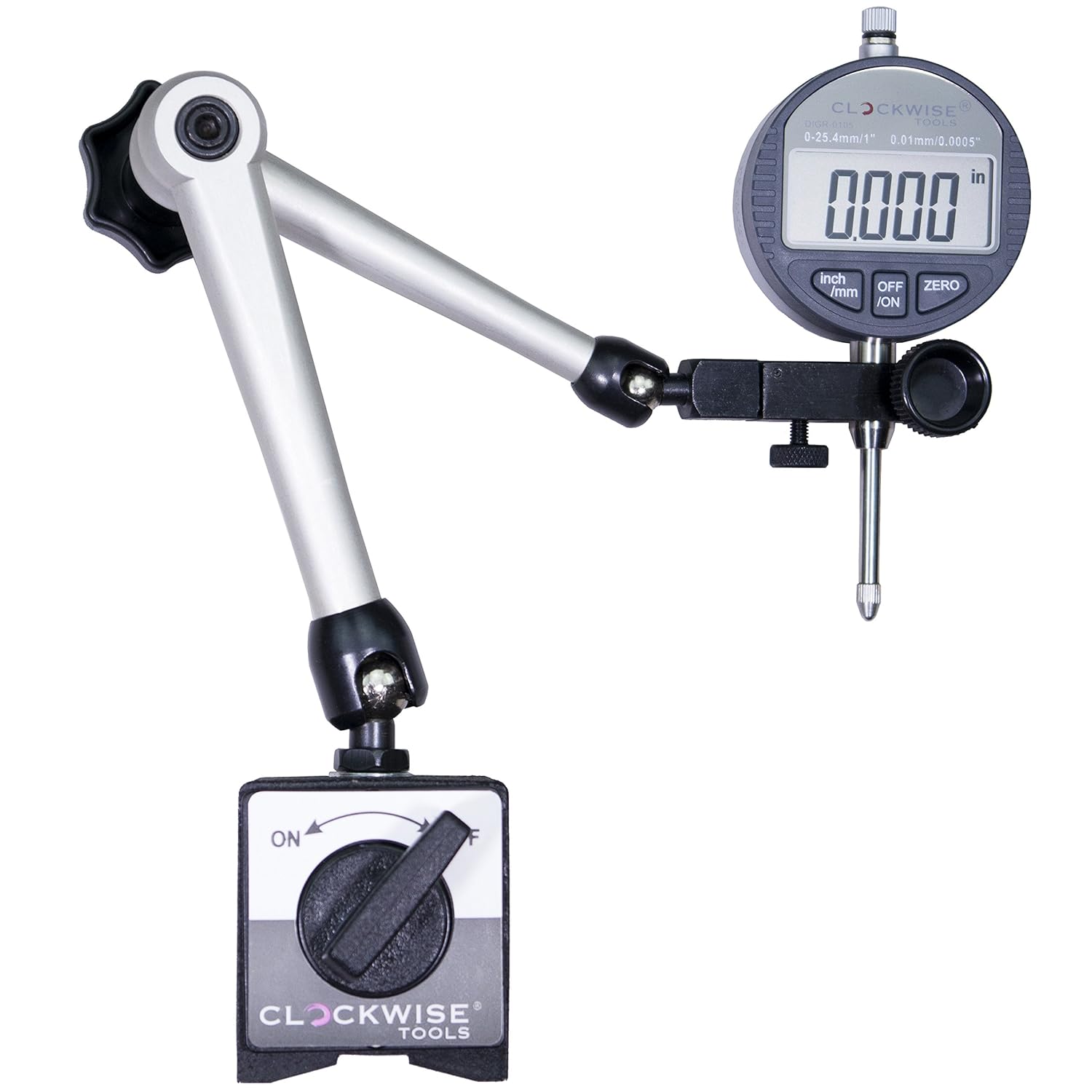
Figure 1: The Clockwise Tools DIBR-0105 Digital Indicator mounted on its magnetic base holder stand.
2. What's in the Box
Upon opening the package, verify that all components are present and undamaged:
- Digital Indicator (DIBR-0105)
- Magnetic Base Holder Stand
- Batteries (pre-installed or separate)
- User Guide (this document)
- Certificate of Calibration
- Lug Back (alternative mounting option)

Figure 2: The DIBR-0105 Digital Indicator and its accessories neatly organized within the protective carrying case.
3. Key Features
- Dual Unit Conversion: Supports both inch and metric readings.
- Large LCD Display: 1.6" x 0.7" screen for clear visibility.
- Auto-Off Function: Powers off after 5-7 minutes of inactivity, retaining zero position upon restart.
- High Precision: 0-1" (25.4mm) measuring range, 0.0005" (0.01mm) resolution, and ±0.001" (0.03mm) accuracy.
- Strong Magnetic Base: Two magnetic faces with up to 176 lbs pull force (optimal on 30mm+ thick metal/steel).
- Versatile Mounting: Flat back and lug back options (6.5mm hole), 3/8" stem diameter, UNF 4-48 threaded tip.
- RS232 Data Transfer: Port for PC connectivity (requires "Clockwise Tools DTCR-01" cable, sold separately).
- Professional Certification: Includes a calibration certificate.
4. Setup Instructions
Follow these steps to assemble and prepare your digital indicator for use:
- Attach the Indicator to the Stand:
Insert the stem of the digital indicator into the clamp on the magnetic base holder stand. Ensure it is seated properly.

Figure 3: Detail showing the indicator stem inserted into the holder. The knob labeled "Tighten Indicator" secures the indicator, while the "Adjusting" knob allows for fine positioning.
Tighten the securing knob (as indicated in Figure 3) to firmly hold the indicator in place. Do not overtighten.
- Positioning the Magnetic Base Arm:
The magnetic base holder stand features articulated arms for flexible positioning. To adjust the arm, loosen the central knob (labeled 'A' in Figure 4). Position the indicator as desired, then twist knob 'A' to lock all joints (A, B, and C) simultaneously.

Figure 4: The articulated arm of the magnetic base. Twisting knob 'A' locks joints 'A', 'B', and 'C' to secure the indicator's position.
- Activating the Magnetic Base:
Place the magnetic base on a clean, flat ferrous surface. Turn the lever on the magnetic base to the "ON" position to activate the magnet. Ensure the base is securely attached before proceeding with measurements. Turn the lever to "OFF" to release the base.
Note: The magnetic force is strongest on metal surfaces 30mm or thicker. Thinner surfaces may result in reduced holding power.
- Battery Installation (if not pre-installed):
If the indicator display does not turn on, it may require battery installation or replacement. Refer to the battery compartment on the back of the indicator for instructions on opening and inserting the correct battery type (typically a CR2032 coin cell battery).
5. Operating Instructions
This section details the functions and operation of your digital indicator.
5.1 Power On/Off
- Press the ON/OFF button to turn the indicator on.
- Press and hold the ON/OFF button for a few seconds to turn the indicator off.
- The indicator will automatically power off after 5-7 minutes of inactivity to conserve battery. The last zero position will be retained when powered back on.
5.2 Inch/Metric Conversion
The indicator supports both imperial (inch) and metric (millimeter) units.
- Press the IN/MM button to switch between inch and millimeter display modes.
- The current unit will be displayed on the LCD screen.

Figure 5: The indicator's display showing a measurement in inches and then the same measurement converted to millimeters, highlighting the IN/MM conversion function.
5.3 Zero Setting
To set the current position as zero for relative measurements:
- Position the indicator's contact point at the desired reference surface.
- Press the ZERO button. The display will reset to "0.0000" (or "0.00" in metric), and subsequent movements will be measured relative to this point.
5.4 Data Transfer (Optional)
The DIBR-0105 indicator is equipped with an RS232 port for data output to a computer. This feature requires a separate data cable.
- Obtain the "Clockwise Tools DTCR-01" data cable (sold separately).
- Connect one end of the DTCR-01 cable to the RS232 port on the indicator.
- Connect the other end of the DTCR-01 cable to your computer's USB port.
- Use appropriate software on your computer to receive data from the indicator.

Figure 6: The DIBR-0105 indicator connected to a laptop via the optional DTCR-01 data cable, demonstrating its data transfer capability. The laptop is not included with the indicator.
Note: The DTCR-01 cable is specifically designed for RS232 to USB conversion and is not a standard USB cable.
6. Maintenance
Proper maintenance ensures the longevity and accuracy of your digital indicator.
- Cleaning: Wipe the indicator and magnetic base with a clean, dry, soft cloth after each use. Avoid using solvents or harsh chemicals, which can damage the display or finish.
- Storage: Store the indicator in its protective case in a dry, dust-free environment when not in use. Avoid extreme temperatures and humidity.
- Battery Replacement: If the display becomes dim or erratic, replace the battery (CR2032). Ensure correct polarity during installation.
- Calibration: While the indicator comes with a calibration certificate, periodic re-calibration by a qualified technician is recommended for critical applications to maintain accuracy.
- Magnetic Base Care: Keep the magnetic faces clean and free of debris to ensure maximum holding force.
7. Troubleshooting
If you encounter issues with your digital indicator, refer to the following common problems and solutions:
| Problem | Possible Cause | Solution |
|---|---|---|
| Display does not turn on. | Dead or improperly installed battery. | Replace the battery (CR2032) ensuring correct polarity. |
| Inaccurate readings. | Dirty contact point; indicator not properly zeroed; environmental factors (temperature fluctuations). | Clean the contact point. Re-zero the indicator. Ensure stable operating conditions. Consider professional re-calibration if issues persist. |
| Magnetic base not holding securely. | Magnetic lever in "OFF" position; dirty magnetic face; thin or non-ferrous surface. | Ensure lever is in "ON" position. Clean magnetic faces. Use on appropriate ferrous surfaces (30mm+ thickness recommended). |
| Data transfer not working. | Incorrect cable; software issue; loose connection. | Ensure you are using the "Clockwise Tools DTCR-01" cable. Check software settings and connections. |
8. Specifications
| Feature | Detail |
|---|---|
| Model Number | DIBR-0105 |
| Measuring Range | 0-1 inch (0-25.4 mm) |
| Resolution | 0.0005 inch (0.01 mm) |
| Accuracy | ±0.001 inch (±0.03 mm) |
| Display | LCD, 1.6" x 0.7" |
| Units | Inch / Millimeter (switchable) |
| Auto-Off | 5-7 minutes |
| Stem Diameter | 3/8 inch |
| Threaded Tip | UNF 4-48 |
| Magnetic Base Pull Force | Up to 176 lbs (on 30mm+ thick metal) |
| Data Output | RS232 port (requires separate DTCR-01 cable) |
| Power Source | CR2032 battery |
| Product Dimensions | 4.88 x 2.19 x 1 inches (Indicator only) |
| Weight | 4.04 Pounds (Total package weight) |
9. Warranty and Support
For warranty information and customer support, please refer to the documentation included with your product or visit the official Clockwise Tools website.
You can also visit the Clockwise Tools Store on Amazon for additional product information and support resources.


