
1. Introduction
The VICTOR VC890C+ is a stable, battery-driven digital multimeter featuring a 28mm LCD display. It is designed for a wide range of measurements including DC voltage (DCV), AC voltage (ACV), DC current (DCA), AC current (ACA), resistance, capacitance, frequency, diode, and transistor tests, as well as continuity testing. This meter also includes convenient features such as auto power-off, backlight, True RMS, Non-Contact Voltage (NCV) measurement, and a flashlight function. Built around an integrated circuit, it serves as an ideal tool for laboratory, factory, and general household electrical tasks.
This manual provides detailed instructions for the safe and effective use of your VICTOR VC890C+ Digital Multimeter.
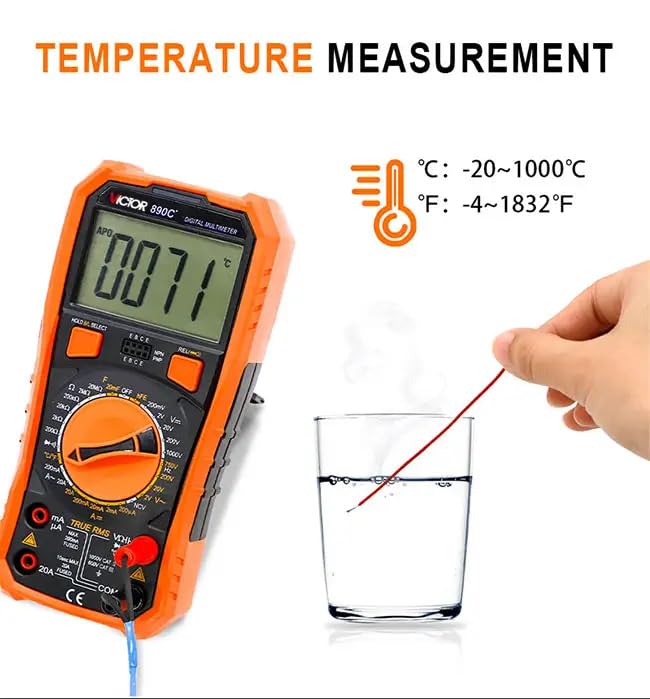
Figure 1: Front view of the VICTOR VC890C+ Digital Multimeter.
2. Safety Information
To ensure safe operation and to avoid damage to the meter, please read this manual carefully before use and observe all safety warnings. Always adhere to local and national safety codes.
- Do not exceed the maximum input values for any function.
- Do not use the meter if it or the test leads appear damaged.
- Ensure the function switch is in the correct position for the measurement being performed.
- Be cautious when working with voltages above 30V AC RMS, 42V peak, or 60V DC, as these pose a shock hazard.
- Always disconnect the test leads from the circuit before changing the function switch position.
- Remove the test leads from the meter before opening the battery cover or case.
- Replace the battery immediately when the low battery indicator appears to ensure accurate readings.
- Do not operate the meter in explosive gas, vapor, or dusty environments.
- The meter features shock-proof protection, but avoid unnecessary drops or impacts.
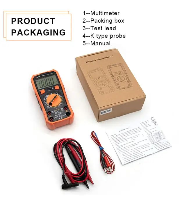
Figure 2: The multimeter features a multi-layer protective cover designed for scratch and impact resistance.
3. Product Features
The VICTOR VC890C+ Digital Multimeter offers a range of advanced features for versatile electrical testing:
- Large LCD Display: Clear 28mm display for easy reading of measurements.
- True RMS: Provides accurate readings for non-sinusoidal AC waveforms.
- Non-Contact Voltage (NCV) Measurement: Detects AC voltage without physical contact, enhancing safety.
- Torch Function: Integrated flashlight for working in dimly lit areas.
- Auto Power Off: Conserves battery life by automatically shutting down after a period of inactivity.
- Backlight: Illuminates the display for visibility in low-light conditions.
- Diode & Continuity Test: Essential functions for checking circuit integrity and component functionality.
- Capacitance Upgrade: Enhanced capacitance measurement range up to 20mF.
- Shock Proof Protection: Durable design with multi-layer protection against drops and impacts.
- Function Protection: Built-in protection for various measurement ranges.
4. Package Contents
Upon unpacking, please verify that all items listed below are included and in good condition:
- VICTOR VC890C+ Digital Multimeter
- Packing Box
- Test Leads (Red and Black)
- K-Type Thermocouple Probe
- User Manual
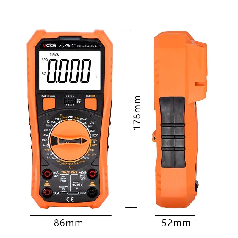
Figure 3: Included components with the VICTOR VC890C+ Digital Multimeter.
5. Setup
5.1 Battery Installation
The VICTOR VC890C+ requires one LR44 battery (included). To install or replace the battery:
- Ensure the multimeter is turned off and test leads are disconnected.
- Locate the battery compartment cover on the back of the meter.
- Use a screwdriver to loosen the screw(s) and remove the cover.
- Insert the LR44 battery, observing the correct polarity (+ and -).
- Replace the battery cover and secure it with the screw(s).
5.2 Connecting Test Leads
Proper connection of test leads is crucial for accurate and safe measurements:
- Insert the black test lead into the "COM" (common) jack.
- For most voltage, resistance, capacitance, frequency, diode, and continuity measurements, insert the red test lead into the "VΩHzCAP" jack.
- For current measurements (mA), insert the red test lead into the "mA" jack.
- For high current measurements (up to 20A), insert the red test lead into the "20A" jack.
- For temperature measurements, connect the K-type thermocouple probe to the designated jacks (usually marked with temperature symbols or specific ports).
6. Operating Instructions
6.1 General Operation
Turn the rotary switch to the desired function. The display will show the measurement. Use the "HOLD/SELECT" button to freeze the current reading or to switch between functions on a multi-function range (e.g., AC/DC, Diode/Continuity).
6.2 DC Voltage Measurement (DCV)
- Connect the red test lead to the "VΩHzCAP" jack and the black test lead to the "COM" jack.
- Set the rotary switch to the desired DCV range (e.g., 2V, 20V, 200V, 1000V). If unsure, start with the highest range.
- Connect the test leads in parallel to the circuit or component being measured.
- Read the voltage value on the display.
6.3 AC Voltage Measurement (ACV)
- Connect the red test lead to the "VΩHzCAP" jack and the black test lead to the "COM" jack.
- Set the rotary switch to the desired ACV range (e.g., 2V, 20V, 200V, 750V).
- Connect the test leads in parallel to the AC source or component.
- Read the voltage value on the display.
6.4 DC Current Measurement (DCA)
- Important: Current measurements require breaking the circuit and connecting the meter in series.
- Connect the black test lead to the "COM" jack.
- For mA range, connect the red test lead to the "mA" jack. For 20A range, connect to the "20A" jack.
- Set the rotary switch to the appropriate DCA range (e.g., 200uA, 2mA, 20mA, 200mA, 20A).
- Open the circuit and connect the meter in series with the load.
- Read the current value on the display.
6.5 AC Current Measurement (ACA)
- Follow the same series connection procedure as for DC current.
- Set the rotary switch to the appropriate ACA range (e.g., 200mA, 20A).
- Read the current value on the display.
6.6 Resistance Measurement
- Ensure the circuit is de-energized before measuring resistance.
- Connect the red test lead to the "VΩHzCAP" jack and the black test lead to the "COM" jack.
- Set the rotary switch to the Ω (Ohms) range.
- Connect the test leads across the component to be measured.
- Read the resistance value on the display.
6.7 Capacitance Measurement
- Ensure the capacitor is fully discharged before measurement to prevent damage to the meter.
- Connect the red test lead to the "VΩHzCAP" jack and the black test lead to the "COM" jack.
- Set the rotary switch to the CAP (Capacitance) range.
- Connect the test leads across the capacitor terminals.
- Read the capacitance value on the display.

Figure 4: The multimeter offers an upgraded capacitance range, making it suitable for various capacitor measurements.
6.8 Frequency Measurement
- Connect the red test lead to the "VΩHzCAP" jack and the black test lead to the "COM" jack.
- Set the rotary switch to the Hz (Frequency) range.
- Connect the test leads in parallel to the circuit where frequency is to be measured.
- Read the frequency value on the display.
6.9 Diode Test
- Ensure the circuit is de-energized.
- Connect the red test lead to the "VΩHzCAP" jack and the black test lead to the "COM" jack.
- Set the rotary switch to the Diode symbol.
- Connect the red lead to the anode and the black lead to the cathode of the diode. A forward voltage drop will be displayed.
- Reverse the leads. The display should show "OL" (Open Loop) for a good diode.
6.10 Transistor Test
The VC890C+ includes an hFE socket for testing NPN and PNP transistors. Insert the transistor leads into the corresponding EBC (Emitter, Base, Collector) holes on the meter and set the rotary switch to the hFE position to measure the transistor's DC current gain.
6.11 Continuity Test
- Ensure the circuit is de-energized.
- Connect the red test lead to the "VΩHzCAP" jack and the black test lead to the "COM" jack.
- Set the rotary switch to the Continuity symbol (often shared with Diode test, use SELECT button if needed).
- Connect the test leads across the component or wire. A continuous beep indicates a low resistance path (continuity).
6.12 Non-Contact Voltage (NCV) Measurement
The NCV function allows for safe detection of AC voltage without direct contact.
- Set the rotary switch to the NCV position.
- Bring the top part of the meter (NCV sensor area) close to the conductor or outlet.
- If AC voltage (48V-220V) is detected, the red indicator light will flash, and the buzzer will beep.
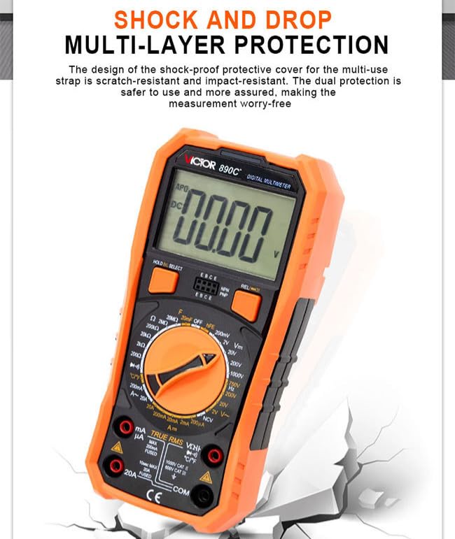
Figure 5: NCV function allows for non-contact detection of AC voltage, indicated by flashing light and buzzer.
6.13 Temperature Measurement
The multimeter can measure temperature using the included K-type thermocouple probe.
- Connect the K-type thermocouple probe to the designated temperature input jacks on the meter.
- Set the rotary switch to the °C/°F position.
- Place the tip of the thermocouple probe on or near the object whose temperature is to be measured.
- Read the temperature value on the display in Celsius or Fahrenheit.

Figure 6: Temperature measurement using the K-type thermocouple probe, showing a range of -20 to 1000°C (-4 to 1832°F).
6.14 Auto Power Off
The meter will automatically power off after approximately 15 minutes of inactivity to save battery life. To reactivate, turn the rotary switch to OFF and then back to the desired function, or press any button.
6.15 Backlight and Flashlight
Press the dedicated backlight button (if available) or the "HOLD/SELECT" button (depending on model variation) to turn on the display backlight. Press it again to turn it off. The flashlight function can typically be activated by a dedicated button or a long press of a specific button, providing illumination for the work area.
7. Maintenance
- Cleaning: Wipe the meter with a damp cloth and mild detergent. Do not use abrasives or solvents.
- Battery Replacement: Replace the battery when the low battery indicator appears on the display. Refer to Section 5.1 for instructions.
- Fuse Replacement: If the current measurement function fails, the fuse may need replacement. Refer to the specifications for the correct fuse type and rating. Fuse replacement should only be performed by qualified personnel.
- Storage: If the meter is not used for an extended period, remove the battery to prevent leakage. Store the meter in a cool, dry place, away from direct sunlight and extreme temperatures.
8. Troubleshooting
If you encounter issues with your multimeter, refer to the following common problems and solutions:
| Problem | Possible Cause | Solution |
|---|---|---|
| No display or dim display | Low battery; Meter off; Poor battery contact. | Replace battery; Turn on meter; Check battery contacts. |
| "OL" (Overload) displayed | Input exceeds selected range; Open circuit (for continuity/resistance). | Select a higher range; Check circuit connection. |
| Incorrect readings | Wrong function selected; Test leads incorrectly connected; Low battery; External interference. | Select correct function; Reconnect leads; Replace battery; Move away from interference sources. |
| Current measurement fails | Blown fuse; Incorrect lead connection; Meter not in series. | Check/replace fuse; Ensure leads are in correct current jacks; Connect meter in series. |
| No continuity beep | Open circuit; High resistance. | Check circuit for breaks; Ensure resistance is below threshold for beep. |
9. Specifications
9.1 General Specifications
| Model | VC890C+ |
| Power Source | 1 x LR44 Battery (included) |
| Product Dimensions (L x W x H) | 20 x 15 x 18 cm (7.87 x 5.91 x 7.09 inches) |
| Item Weight | 500 grams (1.1 lbs) |
| Display | 28mm LCD with Backlight |
| Safety Compliance | CE, FCC, ISO 9001, RoHS |
| Operating Temperature | Up to 50°C |
| Auto Power Off | Yes |
| Included Components | Multimeter, Test Leads, K-Type Probe, Manual |
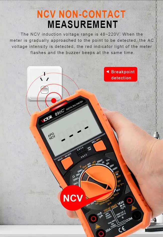
Figure 7: Physical dimensions of the VICTOR VC890C+ Digital Multimeter.
9.2 Electrical Specifications
| Basic Skill | Range | Accuracy |
|---|---|---|
| DC Voltage | 200mV/2V/20V/200V | ± (0.5%+3) |
| 1000V | ± (0.8%+10) | |
| AC Voltage | 2V/20V/200V | ± (0.8%+5) |
| 750V | ± (1.2%+10) | |
| DC Current | 200uA/2mA/20mA | ± (0.8%+5) |
| 200mA | ± (1.2%+8) | |
| 20A | ± (2.0%+5) | |
| AC Current | 200mA | ± (1.2%+8) |
| 20A | ± (3.0%+10) | |
| Resistance | 200Ω | ± (0.8%+5) |
| 2kΩ/20kΩ/200kΩ/2MΩ | ± (0.8%+3) | |
| 20MΩ | ± (1.0%+25) | |
| Capacitance | 6nF | ± (5.0%+40) |
| 60nF/600nF/6uF/60uF | ± (3.5%+20) | |
| 600uF/6mF | ± (5.0%+20) | |
| 20mF | ± (5.0%+40) |
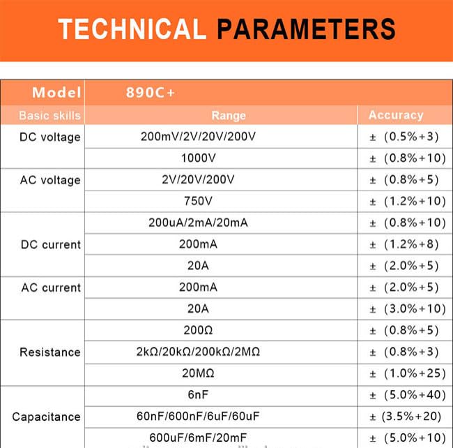
Figure 8: Detailed electrical specifications for the VICTOR VC890C+ Digital Multimeter.
10. Warranty and Support
The VICTOR VC890C+ Digital Multimeter comes with a 1-year warranty from the date of purchase, covering manufacturing defects. This warranty does not cover damage caused by misuse, accidents, unauthorized repairs, or normal wear and tear.
For technical support, warranty claims, or spare parts inquiries, please contact your retailer or the manufacturer's customer service. Please have your product model number (VC890C+) and proof of purchase ready when contacting support.
- Spare parts availability: 3 Years


