
Introduction
This manual provides essential information for the proper installation, operation, and maintenance of your Walfront 16V 83F Capacitor Module. Designed for automotive applications, this super capacitor module offers stable voltage and high energy conversion efficiency. Please read this manual thoroughly before use to ensure optimal performance and safety.
Setup and Installation
Proper installation is crucial for the safe and effective operation of the capacitor module. Always disconnect the vehicle's battery before beginning any electrical work. Consult a qualified automotive technician if you are unsure about any steps.

Figure 1: Top-down view of the Walfront 16V 83F Capacitor Module, showing the six blue capacitors mounted on a green circuit board.
- Safety First: Ensure the vehicle's ignition is off and the negative terminal of the battery is disconnected to prevent electrical shorts or damage.
- Mounting Location: Select a secure, dry, and well-ventilated location for the capacitor module, away from excessive heat or moisture. Ensure the module is firmly mounted to prevent movement during vehicle operation.
- Wiring Connections:
- Connect the positive (+) terminal of the capacitor module to the positive (+) terminal of the vehicle's power system (e.g., amplifier power input or battery positive).
- Connect the negative (-) terminal of the capacitor module to a reliable ground point on the vehicle chassis or the negative (-) terminal of the battery.
- Use appropriate gauge wiring for all connections to handle the current flow.
- Initial Charging: Before reconnecting the battery, it is recommended to pre-charge the capacitor module using a resistor to prevent a sudden current surge. Connect a suitable resistor (e.g., 100 Ohm, 10W) in series with the positive connection for a few minutes until the capacitor voltage stabilizes.
- Final Connection: Once pre-charged, remove the resistor and securely connect the positive terminal of the capacitor module directly to the vehicle's positive power system. Reconnect the vehicle battery's negative terminal.

Figure 2: A detailed view of the capacitor module, highlighting the individual 2.7V 500F capacitors and their series connection on the circuit board.
Operating Principles
The Walfront 16V 83F Capacitor Module is designed to enhance the stability of your vehicle's electrical system, particularly for high-demand components like audio amplifiers. It functions by storing and rapidly releasing electrical energy.
- Voltage Stabilization: The module helps to maintain a stable voltage supply to connected devices, reducing voltage drops during peak power demands. This can lead to improved performance and longevity of electronic components.
- Fast Charging: The super capacitor technology allows for rapid charging, reaching over 95% of its rated capacity within 10 seconds to 10 minutes, depending on the power source.
- Energy Conversion Efficiency: The module boasts high energy conversion efficiency, minimizing power loss and maximizing the benefit to your electrical system.
- Battery Longevity: By providing stable voltage and reducing the strain on the vehicle's battery during high current draws, the capacitor module can contribute to extending the battery's lifespan.

Figure 3: The Walfront capacitor module positioned alongside a modern car, illustrating its intended application in automotive electrical systems.
Maintenance
The Walfront Capacitor Module is designed for long-term, maintenance-free operation. However, periodic checks can help ensure its continued performance.
- Visual Inspection: Periodically inspect the module for any signs of physical damage, loose connections, or corrosion.
- Cleanliness: Keep the module and its connections clean and free from dust, dirt, and moisture. Use a dry, soft cloth for cleaning. Do not use liquid cleaners directly on the module.
- Connection Integrity: Ensure all wiring connections remain tight and secure. Loose connections can lead to poor performance or overheating.
- Environmental Conditions: Ensure the module remains in a dry, well-ventilated area within the vehicle. Avoid exposing it to extreme temperatures or direct sunlight for prolonged periods.
Troubleshooting
If you encounter issues with your capacitor module, refer to the following table for common problems and their potential solutions.
| Problem | Possible Cause | Solution |
|---|---|---|
| Module not charging or low voltage output. | Loose or incorrect wiring connections. Blown fuse in the power line. Faulty power source. | Check all positive and negative connections for tightness and correct polarity. Inspect and replace any blown fuses. Verify the vehicle's power source is functioning correctly. |
| Module overheating. | Poor ventilation. Excessive current draw. Loose connections. | Ensure the module is in a well-ventilated area. Verify the connected load does not exceed the module's capacity. Tighten all connections. |
| No noticeable improvement in system performance. | Module incorrectly sized for the application. Underlying electrical system issues. | Confirm the module's capacitance and voltage rating are appropriate for your specific automotive application. Have the vehicle's electrical system professionally inspected for other potential problems. |
If troubleshooting steps do not resolve the issue, contact Walfront customer support or a qualified technician for further assistance.
Product Specifications
The following table outlines the key technical specifications for the Walfront 16V 83F Capacitor Module.
| Specification | Value |
|---|---|
| Brand | Walfront |
| Model Number | WALFRONT7d5w3vunot |
| Series Connection Rated Voltage | 16 V |
| Series Connection Rated Capacity | 83 F |
| Material | Aluminum |
| Dimensions (Approx.) | 23 x 6.5 x 3.5 cm (9.1 x 2.6 x 1.4 inches) |
| Operating Voltage | 16 Volts |
| Shape | Round (Individual Capacitors) |
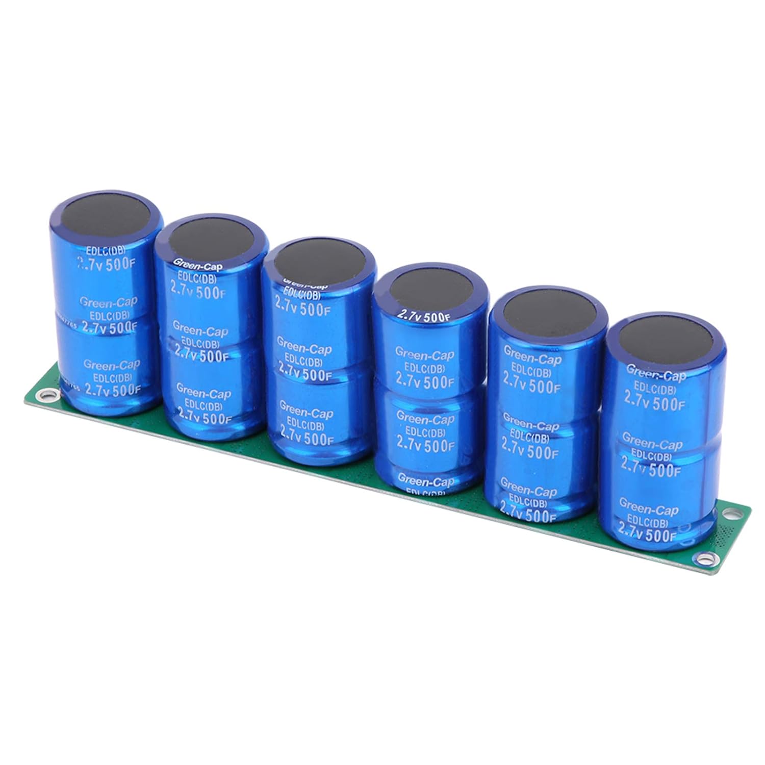
Figure 4: Underside view of the capacitor module's circuit board, showing the balancing circuitry and connection points.