
1. Introduction

Figure 1.1: The HiLetgo W5500 Ethernet LAN Network Module, a compact board for wired network connectivity.
The HiLetgo W5500 Ethernet LAN Network Module provides a reliable and efficient solution for adding wired network connectivity to your microcontroller projects. This module supports various TCP/IP protocols and features a high-speed SPI interface, making it suitable for a wide range of embedded applications. It is designed for compatibility with both 3.3V and 5V systems, offering flexibility for different microcontroller platforms.
2. Product Features
The W5500 module incorporates several key features for robust network integration:
- Hardwired TCP/IP Protocols: Supports TCP, UDP, ICMP, IPv4, ARP, IGMP, and PPPoE directly in hardware.
- Multiple Sockets: Capable of handling 8 independent sockets simultaneously.
- Power Management: Includes Power off mode and Wake on LAN over UDP functionality.
- High-Speed SPI Interface: Utilizes SPI (MODE 0, 3) for efficient data transfer with microcontrollers.
- Integrated Buffers: Features an internal 32Kbytes memory for TX/RX buffers.
- Ethernet PHY: Embedded 10BaseT/100BaseTX Ethernet Physical Layer.
- Auto Negotiation: Automatically detects and configures for full/half duplex and 10/100Mbps speeds.
- Voltage Compatibility: Operates at 3.3V with 5V I/O signal tolerance, simplifying integration.
- Status Indicators: Provides LED outputs for Full/Half duplex, Link status, Speed, and Active data transfer.
3. Package Contents
Each retail package includes the following components:
- 2 x HiLetgo W5500 Ethernet LAN Network Module

Figure 3.1: Contents of the HiLetgo W5500 Ethernet LAN Network Module package, typically including two modules and their protective packaging.
4. Specifications
Detailed technical specifications for the W5500 Ethernet LAN Network Module:
| Specification | Value |
|---|---|
| Main Chip | W5500 |
| Supported Protocols | TCP, UDP, ICMP, IPv4, ARP, IGMP, PPPoE |
| Ethernet PHY | 10BaseT/100BaseTX embedded |
| Interface | SPI (MODE 0, 3) |
| Memory for TX/RX Buffers | Internal 32Kbytes |
| Operating Voltage | 3.3V (with 5V I/O signal tolerance) |
| Dimensions (L x W) | 55.1mm x 28.1mm (approx. 2.17"L x 1.1"W) |
| Simultaneous Sockets | 8 independent |
| Model Name | W5500 |
| Manufacturer Part Number | 3-01-1801 |

Figure 4.1: Physical dimensions of the W5500 module, illustrating its length of 55.1mm and width of 28.1mm.
5. Setup Guide
This section provides instructions for physically connecting and configuring the W5500 Ethernet module with your microcontroller.
5.1 Pinout Description
The W5500 module communicates via a Serial Peripheral Interface (SPI). Understanding the pinout is crucial for correct wiring.
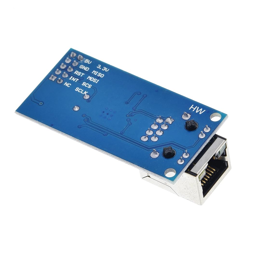
Figure 5.1: Bottom view of the W5500 module, clearly indicating pin labels for connection: 5V, 3.3V, GND, MISO, RST, MOSI, INT, SCS, NC, SCLK.
- 5V: Input for 5 Volt power supply.
- 3.3V: Input for 3.3 Volt power supply.
- GND: Ground connection.
- MISO: Master In Slave Out. SPI data line from the W5500 module to the microcontroller.
- RST: Reset pin for the W5500 module. Typically connected to a digital output on the microcontroller.
- MOSI: Master Out Slave In. SPI data line from the microcontroller to the W5500 module.
- INT: Interrupt pin. Can be used for event-driven communication (optional).
- SCS: Slave Chip Select. SPI chip select pin for the W5500 module.
- NC: No Connection.
- SCLK: Serial Clock. SPI clock signal.
5.2 Hardware Connection Steps
- Power Supply Connection: Connect either the 5V or 3.3V pin to the appropriate power output of your microcontroller or external power supply. Connect the GND pin to the common ground of your system. The module's I/O pins are 5V tolerant, allowing direct connection to 5V logic microcontrollers even when the module is powered by 3.3V.
- SPI Interface Connection: Connect the MISO, MOSI, SCLK, and SCS pins of the W5500 module to the corresponding SPI pins on your microcontroller. Ensure these are correctly mapped according to your microcontroller's datasheet.
- Reset Pin Connection: Connect the RST pin to a digital output pin on your microcontroller. This allows your software to reset the W5500 module programmatically.
- Interrupt Pin Connection (Optional): If your application requires interrupt-driven communication, connect the INT pin to an interrupt-capable digital input pin on your microcontroller.
- Ethernet Cable Connection: Insert a standard RJ45 Ethernet cable into the module's Ethernet port and connect the other end to your network router or switch.


Figure 5.2: Various views of the W5500 module, illustrating the physical layout and connection points for hardware integration.
5.3 Software Setup and Initialization
After hardware connections are complete, configure your microcontroller's software to communicate with the W5500 module.
- Install W5500 Library: Obtain and install a compatible W5500 Ethernet library for your development environment (e.g., Arduino IDE, PlatformIO, STM32CubeIDE). Popular choices include the official WIZnet W5500 library or community-maintained versions.
- Include Header Files: In your project's source code, include the necessary header files for the W5500 library (e.g.,
#include <Ethernet.h>for Arduino). - Define MAC Address: Assign a unique MAC (Media Access Control) address to your module. This is typically an array of 6 bytes.
- Configure Network Parameters: Define the static IP address, subnet mask, gateway IP, and DNS server IP for your module, or configure it to obtain an IP address via DHCP.
- Initialize SPI and W5500: Call the library's initialization function, passing the MAC address and other network parameters. Ensure your microcontroller's SPI peripheral is also initialized correctly before initializing the W5500.
- Test Connection: Implement a simple network test, such as pinging the module's IP address or attempting to connect to a known web server, to verify successful setup.
6. Operating Instructions
This section covers the fundamental operations for network communication using the W5500 module.
6.1 Basic TCP/IP Communication
The W5500 module offloads the TCP/IP stack, simplifying network programming. Here are general approaches for common communication types:
- TCP Client Operation:
- Create an instance of a TCP client object (e.g.,
EthernetClient client;). - Use the
client.connect(server_ip, port);method to establish a connection to a remote server. - Send data using
client.write(data);orclient.print(text);. - Receive data by checking
client.available()and reading withclient.read();. - Close the connection with
client.stop();when communication is complete.
- Create an instance of a TCP client object (e.g.,
- TCP Server Operation:
- Create an instance of a TCP server object (e.g.,
EthernetServer server(port);). - Call
server.begin();to start listening for incoming client connections on the specified port. - Continuously check for new clients using
server.available();. - Once a client connects, use the returned client object to send and receive data as described for TCP client operation.
- Create an instance of a TCP server object (e.g.,
- UDP Communication:
- Create an instance of a UDP object (e.g.,
EthernetUDP Udp;). - Call
Udp.begin(local_port);to start listening for UDP packets on a specific local port. - To send a packet, use
Udp.beginPacket(remote_ip, remote_port);, thenUdp.write(data);, and finallyUdp.endPacket();. - To receive a packet, check
Udp.parsePacket();and then read the data usingUdp.read();.
- Create an instance of a UDP object (e.g.,
For detailed code examples and advanced features, consult the documentation of the specific W5500 library you are using.
6.2 Status LED Indicators
The W5500 module provides visual feedback through its onboard LEDs, indicating various network statuses:
- Link LED: Illuminates when a physical network link is established with a router or switch.
- Speed LED: Indicates the current network connection speed (e.g., on for 100Mbps, off for 10Mbps, or vice-versa depending on implementation).
- Active LED: Flashes to indicate ongoing data transmission or reception activity.
- Full/Half Duplex LED: Shows whether the connection is operating in full-duplex or half-duplex mode.
7. Maintenance
Proper care and maintenance will help ensure the long-term reliability and performance of your W5500 Ethernet module.
- Handling Precautions: Always handle the module by its edges to avoid touching sensitive components. Electrostatic discharge (ESD) can damage electronic components, so use appropriate ESD precautions.
- Environmental Conditions: Store and operate the module in a clean, dry environment. Protect it from dust, moisture, extreme temperatures, and direct sunlight. Avoid environments with corrosive gases or high vibration.
- Cleaning: If cleaning is necessary, use a soft, dry, lint-free cloth or a can of compressed air to remove dust. Do not use liquid cleaners, solvents, or abrasive materials.
- Power Supply: Ensure that the power supply connected to the module is stable and within the specified voltage range (3.3V or 5V). Incorrect voltage or unstable power can lead to malfunction or permanent damage.
- Firmware Updates: Periodically check the WIZnet or HiLetgo website for any firmware updates or library improvements that may enhance performance or address known issues.
8. Troubleshooting
This section provides solutions to common issues you might encounter while using the W5500 Ethernet module.
- Issue: No Link LED Activity / No Network Connection
- Check Ethernet Cable: Ensure the RJ45 Ethernet cable is securely plugged into both the W5500 module and your network router/switch. Try a different cable.
- Verify Network Device: Confirm that your router or switch is powered on and functioning correctly.
- Power Supply: Ensure the W5500 module is receiving stable power (3.3V or 5V) and that the GND connection is solid.
- Module Reset: Try performing a software or hardware reset of the W5500 module.
- Issue: Module Not Responding via SPI
- SPI Connections: Carefully re-check all SPI wiring (MISO, MOSI, SCLK, SCS) between the module and your microcontroller. Ensure no pins are swapped or loose.
- Chip Select (SCS): Verify that the SCS pin is correctly toggled by your microcontroller during SPI communication.
- Reset Pin (RST): Confirm that the RST pin is not held low (in reset state) by your microcontroller. It should be driven high for normal operation.
- SPI Mode: Ensure your microcontroller's SPI peripheral is configured for the correct mode (SPI MODE 0 or 3) as required by the W5500.
- Library Initialization: Confirm that the W5500 library is correctly initialized in your software, including the SPI settings.
- Issue: Network Communication Errors (e.g., cannot ping, cannot connect)
- IP Configuration: Double-check the assigned MAC address, IP address, subnet mask, gateway IP, and DNS server IP in your software. Ensure they are appropriate for your network.
- DHCP Issues: If using DHCP, ensure your DHCP server is active and the module is successfully obtaining an IP address.
- IP Conflicts: Verify that the assigned IP address is not already in use by another device on your network.
- Firewall/Router Settings: Check if any firewall rules on your network or target server are blocking the communication.
- Test Code: Use a known working example sketch from the W5500 library to isolate whether the issue is with your custom code or the module's basic functionality.
- Issue: Intermittent Connectivity or Data Corruption
- Loose Connections: Inspect all wiring for loose connections or cold solder joints.
- Power Stability: Ensure your power supply is stable and can provide sufficient current, especially during peak network activity. Voltage drops can cause instability.
- Noise: In noisy electrical environments, consider adding decoupling capacitors near the module's power pins or using shielded cables for SPI communication.
- SPI Speed: Reduce the SPI clock speed if you are experiencing data corruption over long wires or in noisy environments.
9. Warranty Information
HiLetgo products are typically covered by a standard manufacturer's warranty against defects in materials and workmanship. The duration and specific terms of the warranty may vary based on your region and point of purchase. For detailed warranty information, please refer to the documentation included with your product or contact HiLetgo customer support directly. Please retain your proof of purchase, such as a receipt or order confirmation, as it will be required for any warranty claims.
10. Support
For technical assistance, troubleshooting, or any further inquiries regarding your HiLetgo W5500 Ethernet LAN Network Module, please reach out to HiLetgo support. When contacting support, please be prepared to provide your product model (W5500) and a detailed description of the issue you are experiencing.
- Manufacturer: HiLetgo
- Official Website: www.hiletgo.com
- Support Email: support@hiletgo.com