
1. Introduction
This manual provides detailed instructions for the installation, operation, and maintenance of your Vikye B250 Micro ITX DDR3 Motherboard. This motherboard is designed to support 6th, 7th, 8th, and 9th generation Intel processors, offering a compact solution for various computing needs, including gaming and office applications. Please read this manual thoroughly before proceeding with installation to ensure proper setup and optimal performance.
2. Safety Information
- Always disconnect the power supply from the wall outlet before installing or removing any components.
- Wear an anti-static wrist strap to prevent electrostatic discharge (ESD) damage to components.
- Handle the motherboard by its edges to avoid touching sensitive components.
- Ensure proper ventilation within your PC case to prevent overheating.
- Keep the motherboard away from moisture and extreme temperatures.
3. Package Contents
Verify that all items are present in your package:
- Vikye B250 Micro ITX DDR3 Motherboard
- I/O Shield
- SATA Data Cable(s)
- User Manual (this document)
If any items are missing or damaged, please contact your retailer.
4. Motherboard Layout and Components
Familiarize yourself with the various components and connectors on your motherboard.
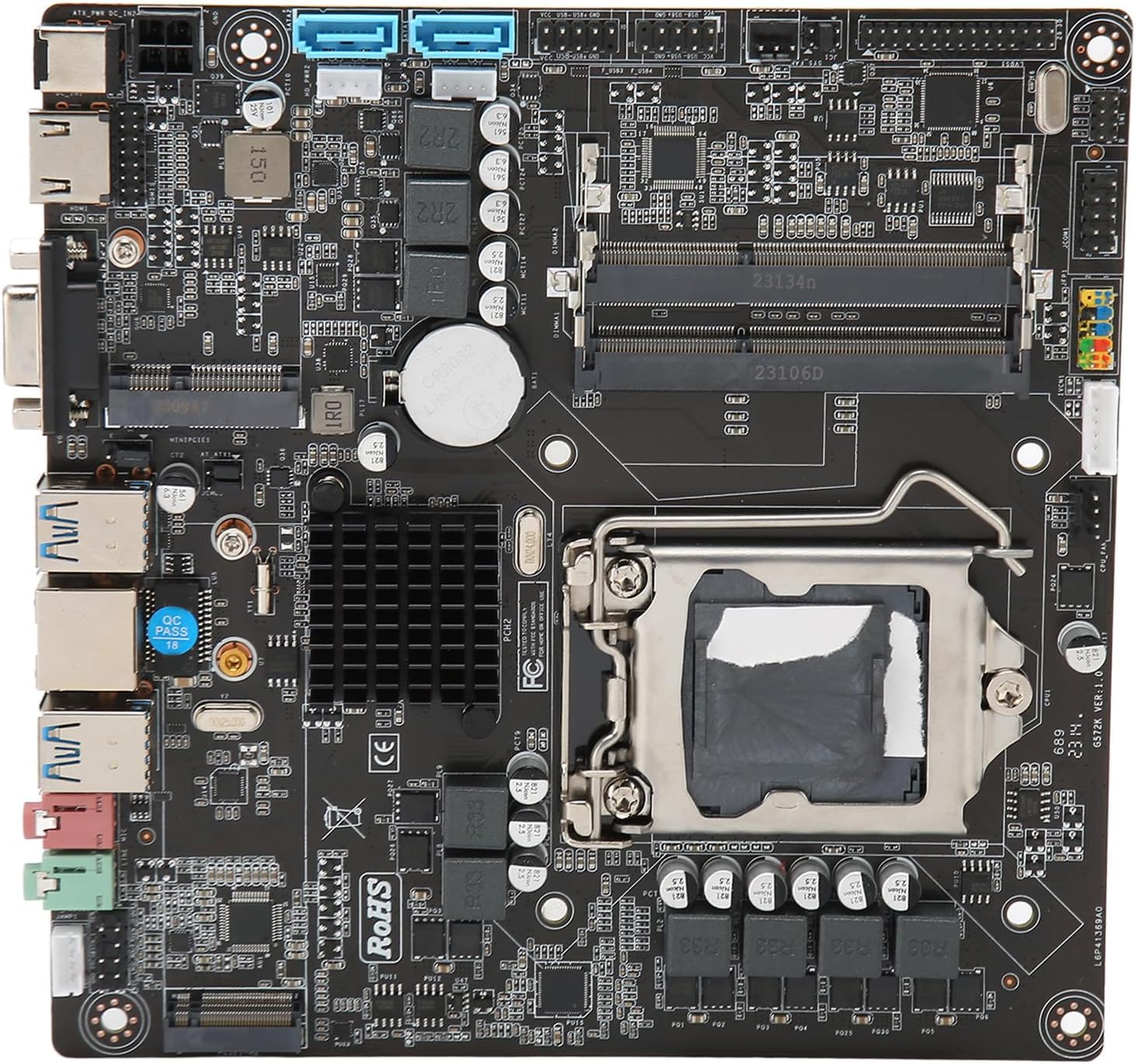
Figure 4.1: Overall view of the Vikye B250 Micro ITX DDR3 Motherboard. This image displays the CPU socket, RAM slots, PCIe slot, SATA ports, and various headers.

Figure 4.2: Detailed diagram showing the location of key components and rear I/O ports, including CPU socket, SATA ports, 12V DC input, HD Multimedia Interface, VGA interface, USB 3.0 ports, Network interface, and Audio ports.
Key Components:
- CPU Socket (LGA1151): Supports 6th, 7th, 8th, and 9th generation Intel Core i3/i5/i7/Pentium/Celeron processors.
- DDR3 DIMM Slots: Two slots supporting dual-channel DDR3 memory up to 1600MHz.
- PCI-Express x16 Slot: For graphics cards or other expansion cards.
- SATA Ports: Multiple ports for connecting storage devices (HDDs/SSDs).
- Rear I/O Ports: Includes USB ports, VGA, RJ45 (Ethernet), and audio jacks.
- Power Connectors: 24-pin ATX power connector and 4-pin 12V CPU power connector.
5. Setup and Installation
Follow these steps to install your motherboard and its components.
5.1. CPU Installation
- Gently lift the CPU socket lever.
- Align the CPU with the socket, ensuring the golden triangle on the CPU matches the triangle on the socket.
- Carefully place the CPU into the socket without forcing it.
- Lower the lever back into place to secure the CPU.
- Apply thermal paste to the CPU and install the CPU cooler according to its instructions.
5.2. RAM Installation
- Open the clips at both ends of the DDR3 DIMM slots.
- Align the notch on the DDR3 memory module with the key in the DIMM slot.
- Insert the memory module firmly into the slot until the clips snap into place.
- For dual-channel operation, install memory modules in matching slots as indicated in the motherboard manual (typically alternating slots).
5.3. Storage Device (SATA) Installation
- Connect one end of the SATA data cable to a SATA port on the motherboard.
- Connect the other end of the SATA data cable to your HDD or SSD.
- Connect a SATA power cable from your power supply unit (PSU) to the storage device.
5.4. Expansion Card (PCIe) Installation
- Locate the PCI-Express x16 slot.
- Remove the corresponding expansion slot cover from your PC case.
- Align your graphics card or other PCIe expansion card with the slot and press down firmly until it is seated correctly.
- Secure the card with a screw to the PC case.
- If required, connect auxiliary power cables from your PSU to the graphics card.
5.5. Power Connections
- Connect the 24-pin ATX main power connector from your PSU to the corresponding header on the motherboard.
- Connect the 4-pin 12V CPU power connector from your PSU to the header near the CPU socket.
5.6. Front Panel Connections
Connect the cables from your PC case's front panel (USB, audio, power button, reset button, HDD LED, power LED) to the corresponding headers on the motherboard. Refer to the motherboard diagram (Figure 4.2) and the small labels on the motherboard for correct pin assignments.
6. Operating Instructions
6.1. First Boot
- After assembling all components, connect your monitor, keyboard, and mouse.
- Connect the power cord to the PSU and turn on the power switch on the PSU.
- Press the power button on your PC case.
- The system should power on, and you should see a display on your monitor.
6.2. BIOS/UEFI Setup
During startup, press the designated key (usually DEL or F2) to enter the BIOS/UEFI setup utility. Here you can configure system settings, boot order, and monitor hardware status.
6.3. Driver Installation
After installing your operating system, install the necessary drivers for the motherboard's chipset, audio, LAN, and any other integrated components. These drivers are typically provided on a support CD or can be downloaded from the manufacturer's website.
7. Maintenance
- Cleaning: Regularly clean dust from inside your PC case and motherboard components using compressed air. Ensure the system is powered off and unplugged before cleaning.
- BIOS Updates: Periodically check the manufacturer's website for BIOS/UEFI updates. Updates can improve stability, add support for new hardware, or fix bugs. Follow the update instructions carefully to avoid system damage.
- Cable Management: Ensure cables are neatly routed to improve airflow and prevent interference.
8. Troubleshooting
This section addresses common issues you might encounter.
| Problem | Possible Solution |
|---|---|
| No power / System does not turn on | Check PSU connections (24-pin ATX, 4-pin CPU), ensure PSU switch is on, verify front panel power button connection. |
| No display on monitor | Ensure monitor is connected and powered on. Check graphics card seating and power connections. Try integrated graphics (VGA) if available. Reseat RAM modules. |
| System reboots unexpectedly | Check CPU cooler installation and thermal paste. Ensure adequate case ventilation. Test RAM modules individually. |
| Operating system not detected | Verify SATA cable connections to storage devices. Check boot order in BIOS/UEFI. Ensure OS is properly installed. |
| USB devices not working | Ensure front panel USB headers are correctly connected. Check for updated USB drivers. Test devices in different ports. |
9. Specifications
Detailed technical specifications for the Vikye B250 Micro ITX DDR3 Motherboard.
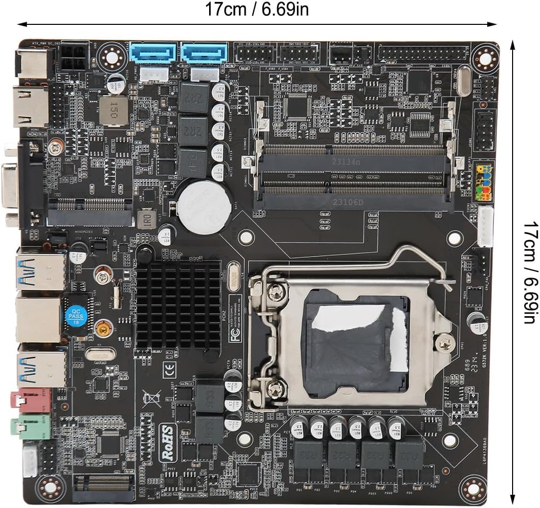
Figure 9.1: Motherboard dimensions (17cm x 17cm).
| Feature | Specification |
|---|---|
| Brand | Vikye |
| Model | B250 Micro ITX |
| CPU Socket | LGA1151 (Supports 6th, 7th, 8th, 9th Gen Intel Processors) |
| Chipset | B250 |
| Memory Type | DDR3 |
| Memory Slots | 2 x DDR3 DIMM (Dual Channel) |
| Max Memory Capacity | 16 GB |
| Memory Clock Speed | 1600 MHz |
| Graphics Interface | Integrated, 1 x PCI-Express x16 |
| Storage Ports | 4 x SATA Ports |
| USB Ports (Rear) | 4 x USB 2.0, 2 x USB 3.0 |
| Video Output | VGA, HD Multimedia Interface |
| LAN | RJ45 Network Interface |
| Audio | Integrated Audio |
| Form Factor | Micro ITX (17cm x 17cm) |
| Country of Origin | China |
10. Warranty and Support
This product comes with a standard manufacturer's warranty. For specific warranty terms and conditions, please refer to the documentation provided with your purchase or contact your retailer. For technical support, driver downloads, or further assistance, please visit the official Vikye support website or contact your point of purchase.